![]()
All the settings are managed and stored in databases. For each supplier created corresponds to an "Xlibdata.mdb" database. In order not to make it too heavy, the sections (graphical representation) are stored in files (.xse).
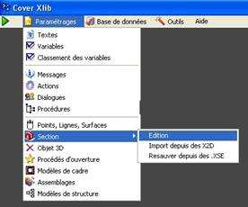
- Creation of a new section: Section\Edition
- Adding points, lines, areas
- Modifications of a section (change of X2D - position of points, lines,...)
- Automatic creation of one or more Sections: Import from X2D
- Recovering sections from Cover Lib: Resave from XSE
Note: See the technical preferences (Tools/Preferences) for automatic placement. from a position point.
Creation of a new section
- Preliminary operation: Cleaning of the file and creation of an x2d
- Imperatives:
- x2d file: The recovery of the section in Cover Xlib is done by means of an .x file. 2d : Step of transformation of the dxf file into a .x2d file.
- Section formed by polygons: the section recovered by Cover Xlib must be formed by polygons: Step of creating polygons from the lines constituting the section (use of of the "polygon creation" tool in Cover 2d).
- Normal and simplified section : The end user will also have the possibility to work in Cover Xpro using the normal or simplified section of the profiles. This concept of section will intervene several times during the use of the software. The simplified section will for example be used for "commercial" wireframe wrapping or again when you want to increase the speed of the camera. The sections have fewer sides, so you can manage large projects without the need for memory. is saturated.
This concept must therefore be integrated in the x2d file in order to be able to parameterize it during the section recovery in Cover Xlib. This is done using the notion of layers in Cover 2d. The normal section will be drawn on the first layer and the simplified section on the second.
"See Cover 2d reminder: polygon creation"
→ Layers organization in the X2D file :
| layer | Denimination |
|---|---|
| Layer 0: | Normal section |
| Layer 1: | Simplified Section |
| Layer 2: | layer reserved for the bulk box |
| Layer 3: | Points |
| Layer 4: | Lines |
| Layer 5: | Surfaces |
Creation of the section :
After having chosen in the menu bar parameter/section/editing, add a new object and
click on the "validate" button ( ![]() ). The editing window for a section opens.
). The editing window for a section opens.
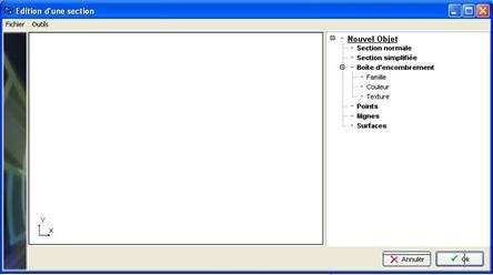
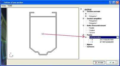
The right part of the window allows the user to visualize the section while the left part contains all the information characterizing the section (the whole being contained in a tree bearing the name of the object). The first thing to do, when it is a new object, is to retrieve the x2d : File/open/.x2d
Note: In a section, the origin of the xy (0.0) marker is always in the corner of bottom left of the section outline box
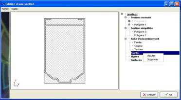
The program automatically locates the section information contained in the x2d (section normal and simplified profile). It also creates a third section representing the of profile dimensions. For each polygon of the normal and simplified section, the following is required define the following information :
Family: Lateral polygon color
- Interior: follows the interior colour of the project
- Exterior: follows the exterior colour of the project
- Raw: is independent of the project colors: choose a color from the palette (as soon as the raw family is selected, a "color" opens.
- Color: color of the section in front view (edge)
- Texture: information to be completed
Note: if in the section retrieval preferences you had chosen to place automatically a position point, this point would be found in the "Points" category of the the object tree structure (see in the technical preferences (Tools/Preferences) for the automatic placement of a position point).
Section registration
Once the operation of colorization of the sections is completed, it is necessary to save the information of the section object in a file with .xse extensions (only when creating a new item) :
- File/Save
- Give a filename (.xse extension) and save it
Remark : The .xse file is to be placed in the "Section" directory of the supplier. (Provider) in progress.
You can then exit the window by clicking on the "OK" button. The new profile object has now been recorded.
Note: It is of course possible to already create points, lines, or surfaces if the user wishes. Otherwise, it is possible to come to the site at any time. Change the information of the object by selecting it.
Adding points, surface lines
See also creating point, line, and area objects (settings/points, lines, areas)
In the "Section" window, select the object to be modified and validate ( ![]() ).
).
The section editing window opens.
It shows the section as it was defined when the object was created. The tree structure contains the categories Points, Lines, and Areas. By right-clicking on one of the categories you can add an element to the section. Let's take as an example the addition of a point in the "carrier" object (identical procedure for a line or a surface):
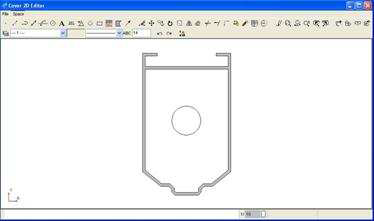
Opening the Cover 2d module. Creating the point in the section and exiting the 2d environment
Note: When you exit Cover 2d you have the choice to save the drawing ("do you want to save drawing?). It is not necessary to save it to record the creation of the point.
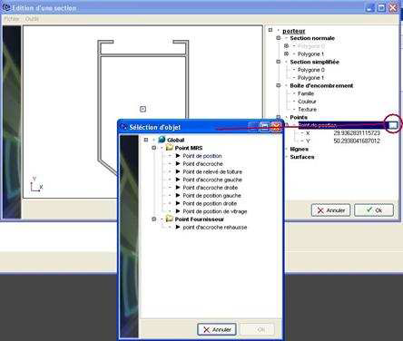
The point is graphically created in the section. But it still needs to be associated with an object (name of the
point). Automatically the program links the "position point" object to the created point. The user
can select another object (MRS point or Provider point) point by means of the button ![]() .
.
Note: to delete a point, a line or a surface, just click (right mouse click) on the element concerned and delete it.
Changing a section
Replacement of the X2D
If, for one reason or another (modification of profiles by the design office, number of segments constituting the section too high,...), changes should be made on the 2D section of the profiles, it is possible to import a new X2D file without lose all the information of points, lines and surfaces present on the section. Instructions :
- In the menu bar of the sectio object, click on File\Import\X2D
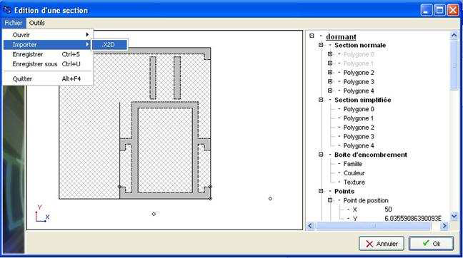
- Choose the X2D file and validate. The new section has been imported and the points, lines, surfaces remained as before. It may be that the position of some points (lines or areas) no longer corresponds exactly to what was set up. previously. However, it is very easy to adjust the shot (see below), change point-line position-surfaces).
- Exit the section by means of the OK button. Changing the position of a point, a line or a surface
To change the position of a point, a line or a surface, simply change the X and Y parameters.
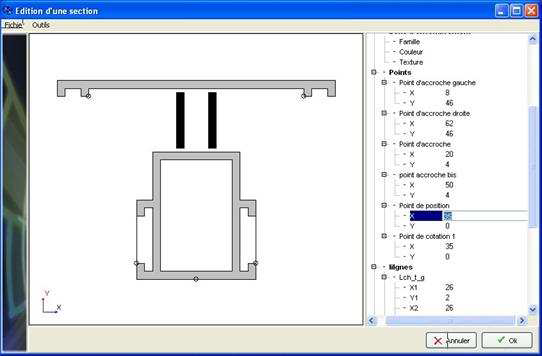
Instructions :
- Click in the field
- Keyboard input
- Enter
Automatic creation of a section: Import from X2D
This allows to automatically generate the sections from the X2D.
Recovering sections from Cover Lib:
Resave from XSE