![]()
Principle of operation :
As a reminder:
- One node = Place of intersection of bars
- One bar = mesh connecting line between two nodes
- A mesh = Surface delimited by bars and whose vertices are nodes.
Each node has a unique code. For each one it will be possible to set up several assembly nodes, i.e. several ways of assembling. Each assembly node contains a variable tree as well as a stacking procedure that the parameterizer is free to create. The variable tree will allow the end user to make local assembly choices for one or more nodes. The assembly procedure will execute, depending on the variable tree, certain actions that will allow the profiles present on the bars of the node to be assembled together.
- Example: In the frame below, a node of the frame is selected.
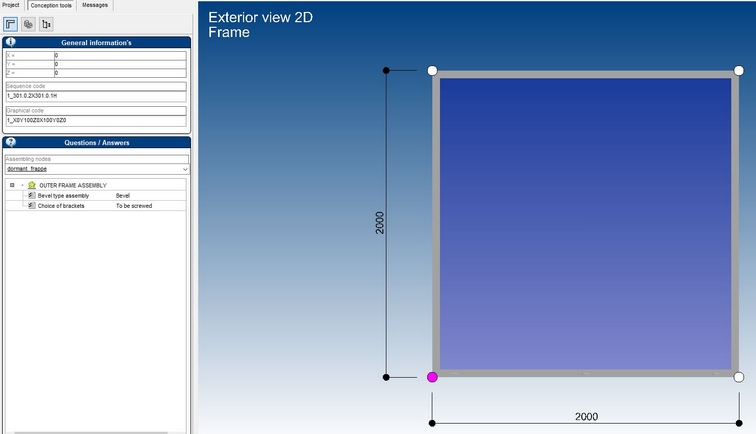
- For this knot, we find:

- The general information:
- This is the sequence code and the graphic code of the selected node. This code is useful for setting up the assembly node.
- Variable tree :
- The variable tree contains a list of the assembly nodes that have been set up for the selected node.
- Depending on the selected assembly node, the corresponding tree is displayed.
In the example, the assembly node "dormant_strike" has been set up. The user can make a choice on the type of assembly (tab-nail) as well as on the choice of brackets.
Note: An assembly node is parameterized for a unique code, and is filtered on the series.
Setting up the assembly node
During the creation of a new object of type "Assembly node", a parameter setting window opens after having clicked on the validate button. ![]()
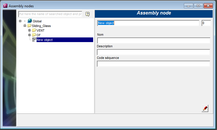
In the left part, it will be possible, as soon as the sequence and graphic code has been specified, to visualize (in a 3D environment) the node you wish to parameterize.
The right-hand part contains all the parameterization information. general information, the variable tree, the assembly procedure.
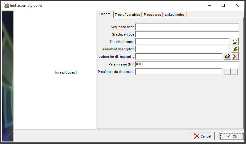
General information
Three pieces of information are needed to identify the node you want to set up: the sequence code, the graphic code (which displays the node preview) and the series.The codes are written by means of automatic entry.
Instruction for the automatic entry of the sequence and graphic code of the node :
- In the program Xlib.exe: Assembly node settings :
- Create a new object and validate

- Create a new object and validate
- Go to the project
- Select the node for which you wish to set up an assembly node in the technic sheet

- go back In the program Xlib.exe
- a new input window has just appeared click "yes"

- now the node gets the sequence code and the graphic code.
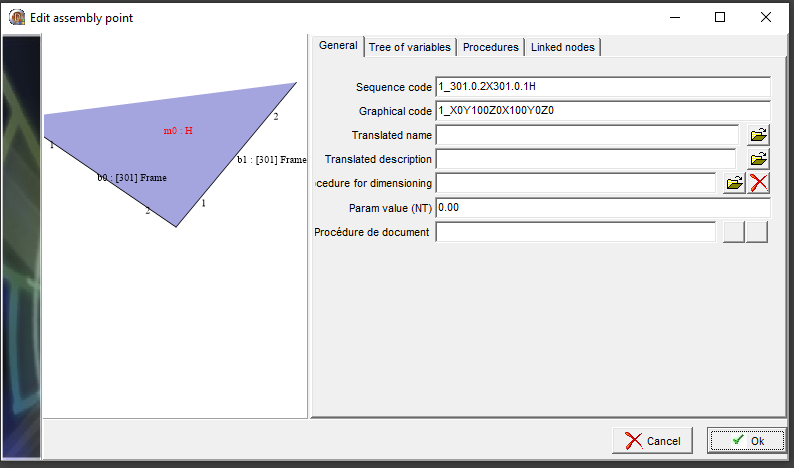
Graphical visualization of the node

- b0 or b1 index of the beam on the node
- 1 or 2 extremity of the beam on the node
- m0 : H index of the mesh on the node
- b0 : [301] Frame : type of beam