Machining
![]()
This tutorial explains how to place a machining between two beams.
Generalities:
Placing a machining is done on the same way as placing an accessory or hardware
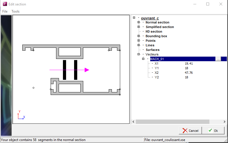
Select the profile you want to machine
- Right click on the vector menu
-Add a vector with the arrow button
-Define a vector- Position (1)
- Length (2)
- Direction (3)


-
Name the vector
-Give a new name
or
- Use the drop down menu to select an existing name

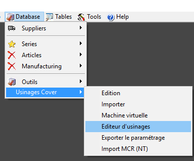
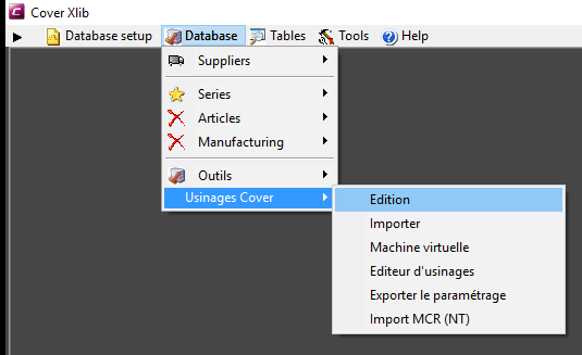
In the database menu
- Select machining editor
-
Name the job
 and validate with the pen
 -
Right click – add a beam
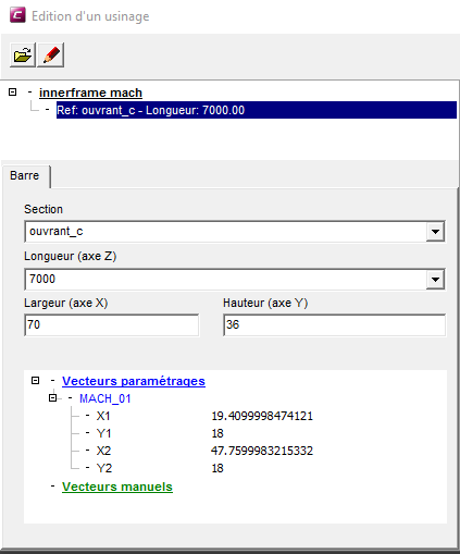
- Select the beam line - Right click - add a profile
- Select the profile line - Right click - add a machining
- Name the machining

-
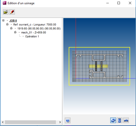
Select the machinig - Right click - add an operation (You can add as many as you wish)
- Select the type of operation
- Hole
- Slot
- Rectangle
- Cylinder
- Macro
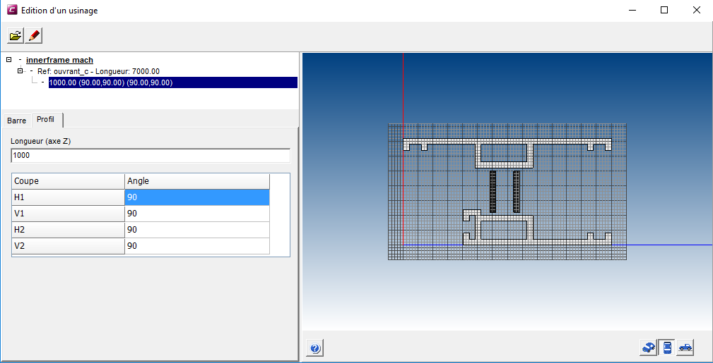
- Select the vector and define the position
(The pink rectangle represents the axis of the machining)
- Valid with the “red pen button”
In the database menu ![]()
- Select edition
-
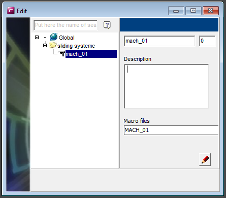
Add a group
- Name the group
- Add an object
- Name the object
- Click on the folder button
- Select the machining
- Valid with the red pen button
The first part is done.
There are different ways (different actions) to place a machining (like there are different ways to place an accessory or hardware (on node, on profile extremity…)
In this example we want to place a machining on the inner frame at the height of the transom. Now we are going to place the machining on the node :
Add an action type “Placing of a machining on node”
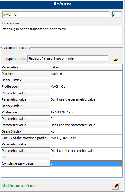
- Machining: select the machining
- Beam 1 index: identification in the node of the reference bar for positioning machining (in this example the inner frame)
- Profile point: point on a profile on beam with index 1.
- Parametric value (optional): parametric value of the profile on beam 1 index
- Beam 2 index: identification in the node of the reference bar for positioning machining (in this example the transom)
- Profile line: line on a profile on beam with index 2 (in this example the axis of the transom).
The intersection between the point (c) and the line (f) determines the insertion point of the machining.
-
Parametric value (optional): parametric value of the profile on beam 2 index
-
Beam 3 index (optional): default value -1
-
Line ID of the machining profile: identification line in the machined profile
-
Parametric value:
-
DZ: movement relative to the calculated point along the Z axis
-
Complementary value: not used
Place the action in the node procedure.
- Refresh the project
- Select the profile on the technical mode
- Right click and see the machining to control (never click on the red pen button)