![]()
Units
- Length: mm
- Angle: degree
- Weight:
- Profile: kg/m
- Filling: kg/m².
Mathematical reminders
-
sine, cosine, tangent and cotangent
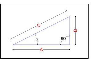
- SINUS : SIN(a) = B / C
- COSINUS : COS(a) = A / C
- TANGENT - COTANGENT :
- TG(a) = SIN(a)/COS(a) = B / A
- COTG(a) = COS(a)/SIN(a) = A / B
-
Determination of X, Y, Z axes and rotation angles The determination of the axes and angles of rotation can be done by means of the right hand rule.
This rule is a way to remember how the axes of 3 directions are related and what is the positive direction of a rotation in this same frame of reference.
It is possible to graphically represent the position of the 3 axes of the X, Y, Z coordinate system in relation to each other and their positive directions.-
Determining the axes:
 The right hand ruler uses, as its name suggests, the fingers of the right hand.
The thumb represents the X axis, the index finger the Y axis and the middle finger the Z axis.
The right hand ruler uses, as its name suggests, the fingers of the right hand.
The thumb represents the X axis, the index finger the Y axis and the middle finger the Z axis.
The positive direction is determined by running the axis from the palm of the hand to the finger -
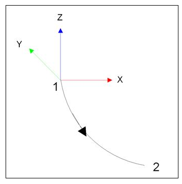
Determination of rotation angle:
 The angle of rotation around an axis is determined by positioning the thumb of the right hand
on it. The curvature of the fingers around this one makes it possible to define the positive
direction of the angle.
The angle of rotation around an axis is determined by positioning the thumb of the right hand
on it. The curvature of the fingers around this one makes it possible to define the positive
direction of the angle.
-
Cutting angles and extrusion of a profile
return to top list
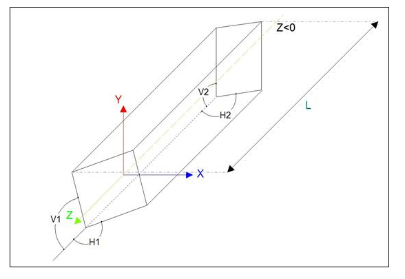
Extrusion of a profile in the X Y Z reference frame :
When the program extrudes a profile onto a bar, the extrusion is done from end 1 to end 2 of the bar in negative Z.
Cutting angles The angles H1, V1, H2 and V2 returned by the program to the manager are calculated as follows:
H1 and V1 are the cutting angles at the end 1 of the profile H2 and V2 are the cutting angles at the end 2 of the profile. H1 and H2 are the angles in the XZ plane V1 and V2 are the angles in the YZ plane The length of the profile "L" is the largest value in Z. It is the distance between the smallest and the largest Z value.
NOTE: For the calculation of the length L, the program is based on the outline box of the profile section.
Example 1: Case of a frame profile assembled at an angle: The angles returned by the program are : V1=90° H1=45° V2=90° H2=135°
Section set up in Cover Xlib (2D):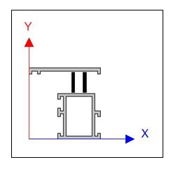
Cutting angle in the extrusion marker (3D):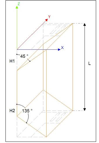
Specific conventions
NOTE: Position of the meshes in relation to the bar: By convention: The mesh on the left of the bar is the mesh on side 1 The mesh on the right side of the bar is the mesh on side 2 The mesh located at the bottom is the mesh on side 3 The mesh on the top of the bar is the mesh on side 4
PoolCover
(for common bars for pool enclosure and conservatory see Conservatory )
| Name | Style of the bar: b.style | Convention section settings | Symbol | Interior angle |
|---|---|---|---|---|
| Portico | 901 Or BSPCPORTICO | Equivalent to the "rafter against wall" and edge rafter bars of a veranda type construction | ||
Wall mounted portico on the left seen from the outside 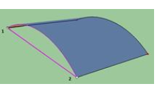 |  | A = 0° | ||
Wall mounted portico on the right seen from outside 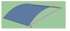 |  | A = -1° | ||
Left edge portico seen from the outside 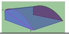 | 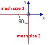 | A = 90° | ||
Right edge portico seen from the outside 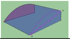 | 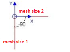 | A = -90° | ||
| Bottom beam | 902 or BSPCBOTTOM | Equivalent to the "ground" bar of a veranda type construction. Only in the case of an adjacent curved mesh 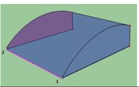 | 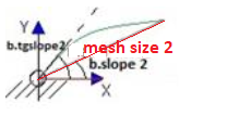 | |
| Inter beam | 903 or BSPCINTER | Equivalent to the "mullion" and "transom" bar of a veranda type construction This property is determined by a difference in slope between the left and right mesh of the bar 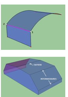 | 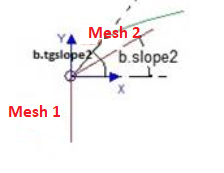 | |
| Horizontal transom | 904 or BSPCTRANSOMH | Equivalent to the property "Traverse between rafters" of a veranda type of construction case of 2 adjacent curved or flat oblique meshes 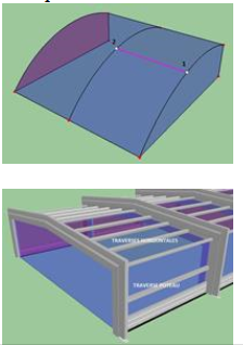 | 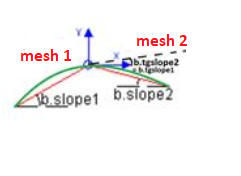 | |
| Vertical transom | 905 or BSPCTRANSOMV | Equivalent to the "Chevron" property of a veranda type construction Case of adjacent curved or flat oblique meshes 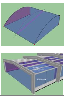 | 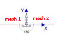 |
- Availability : available in version 2.1
Frame
(convention: always seen from the outside)
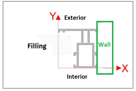
- Visualization of a section : When setting a section, it is done in such a way that the wall is on the right and the inside of the frame on the bottom.
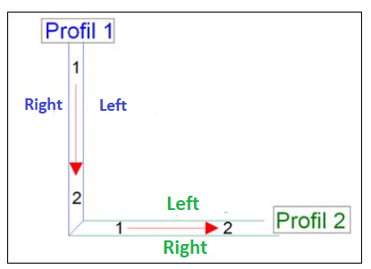
- Direction of travel in a mesh : Determination of the left and right of a profile. NOTE: Frame seen from the outside
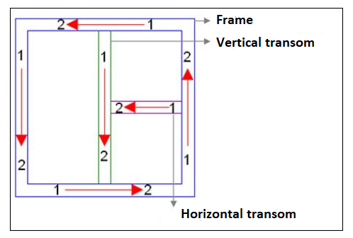
This allows you to distinguish between the left and right sides of a profile (useful when creating assemblies).
-
Example :
-
Bar convention :
| Name | Style of the bar: b.style | Convention section settings | Symbol Cut in bar | Interior angle |
|---|---|---|---|---|
| Frame | 301 or BSFRAME | 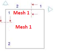 | 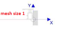 | ` |
| Transom | 304 or BSFRAMETRANSOM | 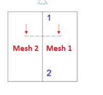 | 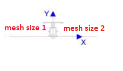 | |
| Crossing beams | 307 or BSCROSSINGBEAMS | See above | 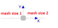 |
Balustrade/Fence
| Name | Style of the bar: b.style | Convention section settings | Symbol Cut in bar | Interior angle |
|---|---|---|---|---|
| STIFFENER | 601 | Section seen from 1 to 2 from top to bottom Z1>Z2 | ||
| 601 | Angular Stiffener : Remark : B.slope1 and b.slope2 are 0. Use b.InteriorAngle for the rotation |  | 0° < A< 360° | |
| 601 | Stiffener against wall on the left, seen from the outside |  | A = 0° | |
| 601 | Stiffener against wall on the right, seen from the outside |  | A = -1° | |
| UPPER RAIL | 602 | 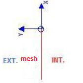 (*) (*) | ||
| LOWER RAIL | 603 | 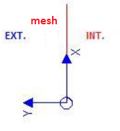 (*) (*) | ||
| INTERMEDIATE RAIL | 604 | 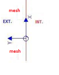 (*) (*) |
(*) Note :
The extrusion conventions for the Smooth bars have been adapted since Cover version 2.0.1.182. Balustrade/Fence settings must be made in version 2.0.1.182 (or later)
Gate :
(convention: always seen from the outside)
| Name | Style of the bar: b.style | Section seen from 1 to 2, top to bottom Z1>Z2 | Symbol Cut in bar | Interior angle |
|---|---|---|---|---|
| Post | 401 | Post on the left seen from the outside | 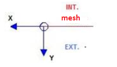 cut : left mesh(Int: low ; Ext: high) cut : left mesh(Int: low ; Ext: high) | A = 0° |
| on the right | 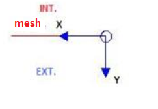 cut : right mesh(Int: low ; Ext: high) cut : right mesh(Int: low ; Ext: high) | A = -1° | ||
| Ground | 402 | at the Bottom ; Direction : from right to left | 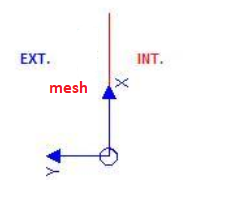 cut : mesh on high(Int: right ; Ext: left) cut : mesh on high(Int: right ; Ext: left) | |
| Higher beam | 403 | at the Top ; Direction : from right to left | 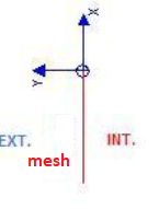 cut : bottom mesh(Int: right ; Ext: left) cut : bottom mesh(Int: right ; Ext: left) | |
| High transom | 404 | at the Top ; Direction : from right to left | cut : bottom mesh(Int: right ; Ext: left) | |
| Lower transom | 405 | at the bottom ; Direction : from right to left | 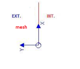 cut : mesh on high(Int: right ; Ext: left) cut : mesh on high(Int: right ; Ext: left) | |
| Intermediate transom | 406 | Inside the frame ; Direction : from right to left | 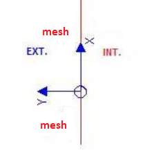 cut : 1 mesh on high and 1 mesh on the bottom (Int: right ; Ext: left) cut : 1 mesh on high and 1 mesh on the bottom (Int: right ; Ext: left) | |
| Mullion | 407 | To the left ; Direction : from top to bottom | 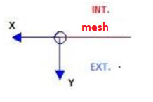 cut: left mesh (Int: low ; Ext: high) cut: left mesh (Int: low ; Ext: high) | A = 0° |
curtain wall :
| Name | Style of the bar: b.style | Convention section settings | Symbol Cut in bar | Interior angle |
|---|---|---|---|---|
| MONTANT 1 | 201 | Section seen from 1 to 2 from top to bottom Z1>Z2 (corresponds to the 180° post) |  | A = 180° |
| MONTANT 2 | 202 | Section seen from 1 to 2 from top to bottom Z1>Z2 (upright with acute angle) |  | 0° < A< 180° |
| MONTANT 3 | 203 | Section seen from 1 to 2 from top to bottom Z1>Z2(Upright with obtuse angle) |  | 180 < A< 360 |
| MONTANT 4 | 204 | Section seen from 1 to 2 from top to bottom Z1>Z2 | | |
| MONTANT 5 | 205 | Section seen from 1 to 2 from top to bottom Z1>Z2 |  | |
| Transom 8 | 208 | Section seen with the mesh on side 1 on the left and side 2 on the right. Remark : the Y axis of the section is always perpendicular to the mesh on side 1 |  | A = 180° |
| Transom 9 | 209 | Section seen with the mesh on side 1 on the left and side 2 on the right.Remark : the Y axis of the section is always perpendicular to the mesh on side 1 |  | A<180° |
| Transom 10 | 210 | Section seen with the mesh on side 1 on the left and side 2 on the right. Remark : the Y axis of the section is always perpendicular to the mesh on side 1 |  | A>180° |
| Transom 11 | 211 | Section seen with the mesh on side 1 on the left Remark : the Y axis of the section is always perpendicular to the mesh on side 1 |  | |
| Transom 12 | 212 | Section seen with the mesh on side 2 on the right.Remark : the Y axis of the section is always perpendicular to the mesh on side 1 |  |
Conservatory :
| Name | Style of the bar: b.style | Convention section settings | Symbol Cut in bar | Interior angle |
|---|---|---|---|---|
| Gutter | 101 | Seen with the roof still on the right  |  : Rem : Relevé Fab. / Com. raising : Rem : Relevé Fab. / Com. raising | 90° < A< 180° |
| Ridge | 102 |  : Rem : Roof raising information (DZ) to be filled in : Rem : Roof raising information (DZ) to be filled in | 0° < A< 180° | |
| Simple ridge | 103 | View with the roof still on the left :  |  : Rem : Roof raising information (DZ) to be filled in : Rem : Roof raising information (DZ) to be filled in | A=0° |
| Rafter | 104 | Section seen from 1 to 2 from top to bottom Z1>Z2 Slope of the bar (roof): b.slope |  | A=180° |
| Hip rafter | 105 | Section seen from 1 to 2 from top to bottom Z1>Z2 Slope of the bar : b.slope |  | 0° < A< 180° |
| Valley | 106 | Section seen from 1 to 2 from top to bottom Z1>Z2 Slope of the bar : b.slope>0 |  | 180° < A< 360° |
| Intermediate | 107 | Section seen as a channel: the ridge is on the right, the channel is on the left REM: b.slope is usually 0°. Use b.slope1 or 2 to access the roof slope |  | |
| Intermediate between posts | 108 | |||
| Oblique upwards gutter | 109 | Seen with roof always on the right Rem.1: Automatic rotation of the sloping gutter by means of the expression : RZ = b.slope2-b.realslope2 / Remark 2: In the case of a saddle bar, this formula will be 0. / Rem.3 : For manufacturing, take into account in the position formula a component in x and y : Dx : (Dy_Cheneau)*sin(RZ) / Dy : (Dy_Cheneau)*cos(RZ) / Note : Dy_Cheneau with b.realslope2 | Same as gutter | |
| Ground | 110 | |||
| Post | 111 | Section seen from 1 to 2 from top to bottom Z1>Z2 | ||
| 111 | Angular post Rem : B.slope1 and b.slope2 are 0 (for a pole). Use b.InteriorAngle for rotation. |  | 0° < A< 360° | |
| 111 | Post against wall on the left, seen from the outside |  | A = 0° | |
| 111 | Post against wall on the right, seen from the outside |  | A = -1° | |
| Side rafter | 112 | Section seen from 1 to 2 from top to bottom Z1>Z2 | ||
| 112 | Left side of the river, seen from the outside |  | A = 90° | |
| 112 | Right side of the river, seen from the outside |  | A = -90° | |
| Wall rafter | 113 | Section seen from 1 to 2 from top to bottom Z1>Z2 | ||
| 113 | Wall on the left seen from the outside |  | A = 0° | |
| 113 | Wall on the right seen from the outside |  | A = -1° | |
| Double ridge | 115 | 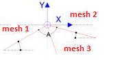 Rem:Fab.raising /Com. raising Rem:Fab.raising /Com. raising | 0°<A<180° | |
| Ridge on level | 116 | 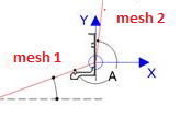 | ||
| Rem:Fab.raising /Com. raising | 180°<A<270° | |||
| Ridge on level (boundary mesh ) | 117 | 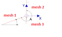 Rem:Fab.raising /Com. raising Rem:Fab.raising /Com. raising | 180°<A<270° | |
| Rafter in plan (at the stop of windows) | 118 | 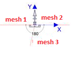 Rem:Com. raising Rem:Com. raising | A=180° | |
| Corner rafter (at the stop of windows) | 119 | 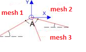 Rem:Com. raising Rem:Com. raising | 0° < A < 180° | |
| Straight valley (boundary mesh ) | 120 | 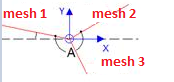 Rem:Com. raising Rem:Com. raising | 180°< A< 360° | |
| Straight valley | 121 | Z1=Z2 Horizontal bar: b.slope=0 | Rem:Com. raising | |
| Straight valley right (boundary mesh ) | 122 | Rem:Com. raising | ||
| Intermediate (boundary mesh ) | 123 | Rem:Com. raising | ||
| Transom roofmesh | 124 | Rem:Com. raising | ||
| Transom roofmesh (at the stop of windows) | 125 | Rem:Com. raising | ||
| Overhang gutter | 150 |  | A=0 | |
| Right gutter | 151 | 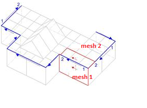 Seen with the flat roof still on the right Seen with the flat roof still on the right | 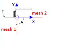 | A=90° |
| Side plate | 152 | 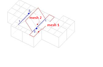 | Seen with the roof still on the right | 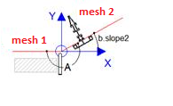 Rem:Fab.raising /Com. raising Rem:Fab.raising /Com. raising |
| Sideboard at the stop of windows | 153 | 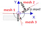 Rem:Fab.raising /Com. raising Rem:Fab.raising /Com. raising | 180°<A<270° | |
| Right Sideboard | 154 | 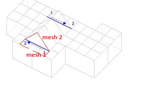 | 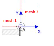 | A=270° |
| Straight curb (boundary mesh ) | 155 | 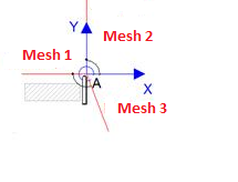 | A=270° | |
| Beam | 156 | 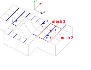 Direction: from top to bottom (-Y) or from right to left (-x) in the construction marker Direction: from top to bottom (-Y) or from right to left (-x) in the construction marker |  | A=180° |
| Linking beam | 157 | 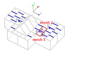 Direction: from top to bottom (-Y) or from right to left (-x) in the construction marker Direction: from top to bottom (-Y) or from right to left (-x) in the construction marker | | A=180° |
| Closing beam | 158 | 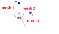 | A=180° | |
| Spacer (boundary mesh ) | 159 | | A=180° | |
| beam against wall | 160 |  Seen with the flat roof still on the right Seen with the flat roof still on the right | 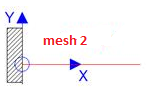 | A=0° |
| Thermal post | 161 | Vertical bar in the 3d marker | A=0° | |
| Stay | 162 | Oblique or horizontal bar in the 3d marker | A=0° | |
| Straight ridge | 163 | 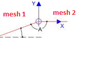 Rem:Fab.raising /Com. raising Rem:Fab.raising /Com. raising | 90°<A<180° | |
| Straight ridge (boundary mesh ) | 164 | 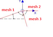 Rem:Fab.raising /Com. raising Rem:Fab.raising /Com. raising | 90°<A<180° |