Actions
Definition
Actions are instructions sent to the program that define the behavior of the items:
- How a profile can be extruded; to the bar? to the mesh? = Profile action positioned
- How a profile is positioned on a bar = Position action
- ….
It is thus pure information, which does not have systems of conditions, of existences.
This is the reason why an action will never be directly associated with an article. It will be necessary to create procedures that will allow the actions to be arranged according to situations (systems of conditions).
When creating a new object of type Action, one must first choose the type of action one wishes to generate. Depending on this type, certain parameters will have to be completed.
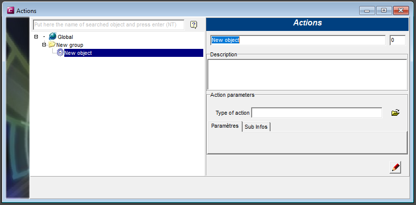
Type of actions
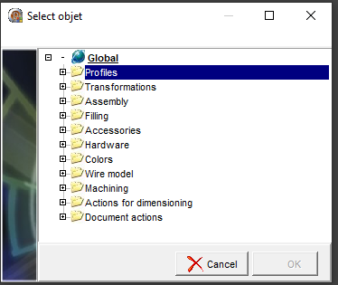
Actions list
Profiles actions list
- Profile position
- Positioned profile action
- Offset profile positioning action with length
- Placement of a profile at a caesura
- Closure extrusion action
Transformations actions list
- Rotation
- Translation XYZ
- Translation X
- Translation Y
- Translation Z
- Translational action (with time)
- Rotating action (with time)
Assembly actions list
- Bevel
- Stop
- Profile lengthening action
- 1-node profile cutting action
- 1-node profile cutting action with assembly line
- Targeted offset action on a point
- Bar offset action
- Expansion action of a profile
- Multi profile cutting action
- Lozenge action
- Profile deletion action by a node
- Twisting action of a profile
- Flush action
- Follows the cutting plans of another profile
- Union profile
Filling actions list
- Cutting
- Multi-fill
- Withdrawal
- Filling action by profiles
- Surface definition point action
- Filling cut by plane
Accessories actions list
- Accessories on profile ends
- Length accessory action
- Accessory placement action at the node
- Action of placing an accessory on an accessory
- Fixed repeat
- Repeat step max-min
- Placement of an accessory at a caesura
Hardware actions list
- Placement of hardware on top of hardware
- Hardware on profile end
- Length hardware
- Hardware with fixed repetition
- Hardware with variable repetition
Colors actions list
Wired actions list
Dynamic opening
- Sash position action
- Hardware property definition action
- Action to define the number of leaves per mesh
- 2D line drawing action
- Drawing action of a cross
- Arc drawing action
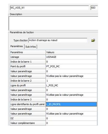
Machining actions list
- Machining action on profile end
- Machining action on accessory
- Machining action at the node
- Machining action with fixed repetition
- Machining action with variable repetition
- Placement of a machining at a caesura
Quotation actions list
- Point definition action at the node
- Bar reference line definition action
- Angular dimensioning action
- Linear quotation action
- Dimensioning action perpendicular to the reference plane
- Overall quotation action
- Leader Line
Profiles
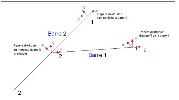
- Definition :The profile action allows a profile item to be extruded onto the bar or onto a mesh adjacent to the bar.

- Use case : pilling-up procedure
- Parameters
- Profile : selection of the profile material to be extruded
- by selection in the list of articles via the "folder" icon

- directly by indicating the identification of the article via the expression editor.

- by selection in the list of articles via the "folder" icon
- Extrusion : extrusion type selection
- On the beam : the profile will be extruded over the entire length of the bar
- Mesh side one : the profile will be extruded the length of the mesh side one
- Mesh side two : the profile will be extruded the length of the mesh side two
- Mesh side three : the profile will be extruded the length of the mesh side three
- Mesh side four : the profile will be extruded the length of the mesh side four
- Profile position : selection of the position action that will specify how the profile is to be positioned on the bar or on another profile.
- Coulour:
- Default : the profile will take the colorization rules defined in the section
- Mill : the profile will not take any colouring
- Revert Out-In : the colours defined in the section will be reversed between inside and outside.
- Interior : the profile will only take the inside color
- Outside : the profile will only take the outside color
- Parametric value: value associated with the profile extruded by this action. This value can be tested later in the parameter setting to differentiate between identical profiles that should have a different behavior.
- Layer: from 0 to n if the profile has to be extruded according to a filler layer
- for simple filling the layer = 0
- for multi-filling the value starts from 1 up to n
- Profile : selection of the profile material to be extruded
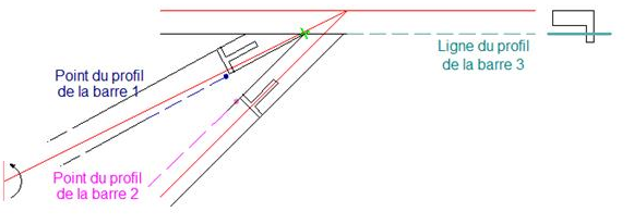
Offset profile positioning action with length
- Definition : the action allows to extrude at the node a length of profile type article with cutting angles.
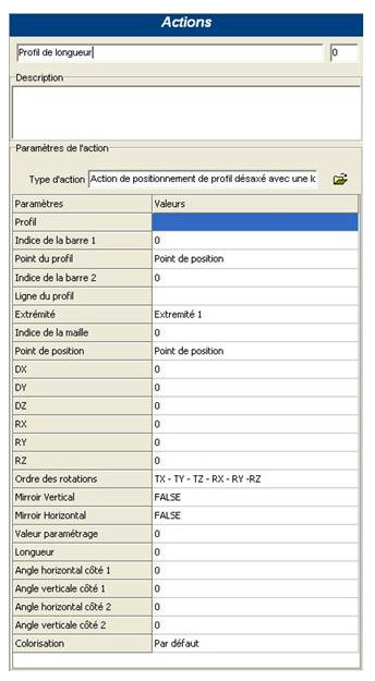
- Use case : Assembly procedure
- Parameters :
- Profile : selection of the profile item from which a defined length is to be extruded.
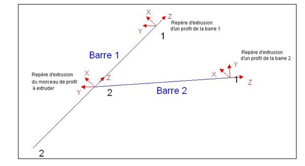
- Index of bar 1 : Index of the bar in the node that will be used as the reference bar for
extruding the profile defined in the first parameter.
The Z axis of the profile to be extruded will be positioned in the same direction as the Z
axis of bar 1.
- Example : Let's take the case of a rafter to hip assembly
- Situation where the index of the bar 1 is the hip:
- Situation where the index of bar 1 is the chevron
- Situation where the index of the bar 1 is the hip:
- Example : Let's take the case of a rafter to hip assembly
- Profile Point: the point on a profile in bar 1 where the position point of the profile piece will come to rest.
- Bar index 2 : Bar index in the node to position the end 1 of the profile piece.
The end 1 of the profile to be extruded over a length will be positioned at the intersection of the bar 1 point and the bar 2 line - Profile Line: line of a profile from bar two allowing the positioning of the profile to be extruded.
- End: Allows you to define the extrusion direction of the profile piece.
- Situation 1: The assembly node corresponds to the end 1 or 2 of bar 1: The actual end
of bar 1 must be entered.
- If node A: Parameter Action endpoint: Endpoint 2
- If node 1: Parameter End of action: End 1
- Situation 2: The join node corresponds to an intermediate node of bar 1.
In this case, entering the end determines the extrusion direction of the profile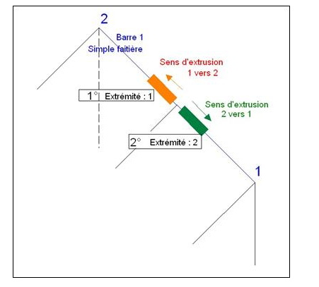
- Situation 2: The join node corresponds to an intermediate node of bar 1.
- Situation 1: The assembly node corresponds to the end 1 or 2 of bar 1: The actual end
of bar 1 must be entered.
- Mesh index : allows the profile to be associated with a mesh
- Position point : insertion point of the profile that will be extruded over a certain length
- DX : displacement along the X axis
- DY : displacement along the Y axis
- DZ : displacement along the Z axis
- RX : rotation along the X axis
- RY : rotation along the Y axis
- RZ : rotation along the Z axis
- Order of rotations :
- Vertical mirror : vertical symmetry of the profile section
- Horizontal mirror : horizontal symmetry of the profile section
- Parameterization value: value associated with the profile extruded by this action. This value can be tested later in the parameterization to differentiate profiles that are identical but should have a different behavior
- Length : formula for the length of the profile
- Remark :
- This is the smallest length on the extrusion axis (Z)
- The program will always take the absolute value of this length (no negative value possible).
- Remark :
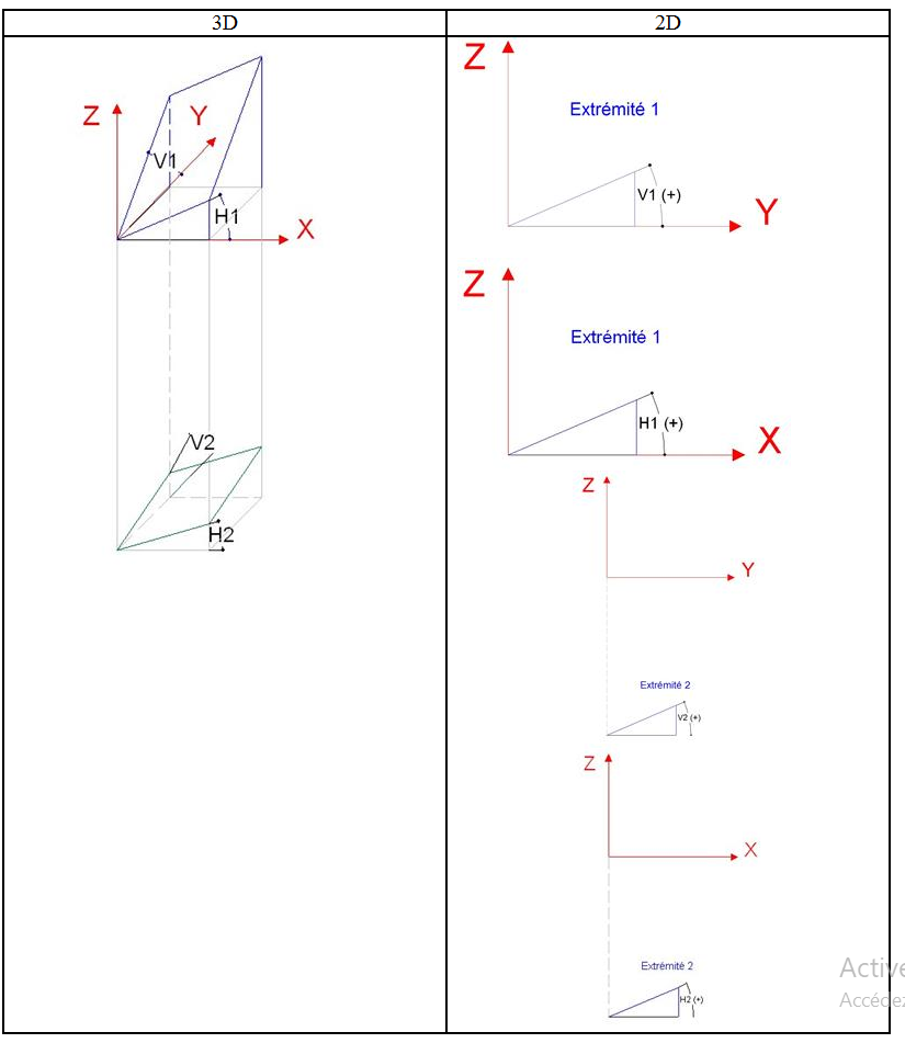
- Horizontal angle side1 : Cut at end 1 in the XZ plane
- Vertical angle side 1 : Cut at end 1 in the YZ plane
- Horizontal angle side 2 : Cut at end 2 in the XZ plane
- Vertical angle side 2 : Cut at end 2 in the YZ plane
- Colorization
- Illustration of sectional drawings:
- Definition : The profile position action allows the user to correctly position an item on a bar. Each item must have this position information. It is in particular by means of this action that the item will be specified its position point (insertion point) on the bar and the point that will serve as a point of attachment to the other profiles stacked by the first one.

- Use case : Positioned profile action
- Parameters :
- DX : X-axis movement
- DY : Y-axis movement
- rz : Z-axis rotation
- Vertical mirror : Apply vertical symmetry to the section => true / false
- Horizontal mirror : Apply horizonal symmetry to the section => true false
- Positionning point : Choice of a point that will allow the section to be placed on the bar or on the attachment point of another profile. The chosen position point must be present in the list of points of the section concerned.
By default, the chosen point is the MRS point "Position point".
- Snap point : choice of a point on which the profiles stacked by the one concerned will be able to hang.
By default, the chosen point is the MRS point "Position point".
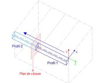
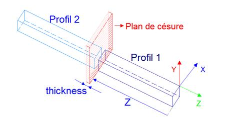
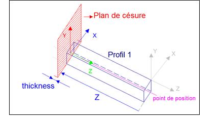
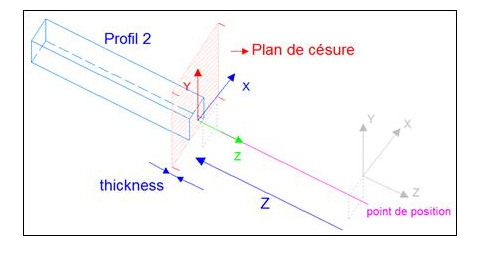
Placement of a profile at a caesura
- Definition
- Use case
- Parameters
- Definition : Enables small pieces of profile to be extruded between the profiles in a open filling with profiles
- Use case : filling with profile on gates, fences and ballustrades,
- Parameters
Transformations
- Definition
- Use case
- Parameters
- Definition
- Use case
- Parameters
- Definition
- Use case
- Parameters
- Definition
- Use case
- Parameters
- Definition
- Use case
- Parameters
Translational action (with time)
- Definition : this action allows to define a translation movement of a leaf - - definition of the process animation
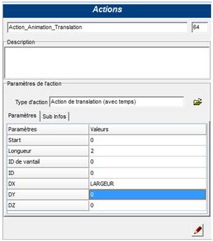
- Use case : Sash definition procedure
- Parameters :
-
Start : Value or expression defining the moment (in seconds) of the start of the action in the animation
-
Length : Value or expression defining the duration of the movement in the animation
-
Leaf ID : Value or expression defining the index of the leaf set in motion by the action
-
ID : Value or expression defining the order in which an action starts in an animation (useful if several actions must start at the same time)
-
DX : Value or expression defining the X displacement of the leaf
-
DY : Value or expression defining the leaf's Y displacement
-
DZ : Value or expression defining the Z displacement of the leaf
-
- availability : Version 2.1
- Definition : this action allows to define a rotation movement of a leaf - - definition of the process animation
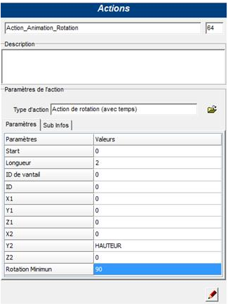
- Use case : Sash definition procedure
- Parameters :
-
Start : Value or expression defining the moment (in seconds) of the start of the action in the animation
-
Length : Value or expression defining the duration of the movement in the animation
-
Leaf ID : Value or expression defining the index of the leaf set in motion by the action
-
ID : Value or expression defining the order in which an action starts in an animation (useful if several actions must start at the same time)
-
X1 : Value or expression defining the X position of the first point of the rotation axis
-
Y1 : Value or expression defining the Y position of the first point of the rotation axis
-
Z1 : Value or expression defining the position in Z of the first point of the rotation axis
-
X2 : Value or expression defining the position in X of the second point of the rotation axis
-
Y2 : Value or expression defining the position in Y of the second point of the rotation axis
-
Z2 : Value or expression defining the Z position of the second point of the rotation axis
-
Minimum rotation : Value or expression defining the amplitude of the rotation movement of the leaf
-
- availability : Version 2.1
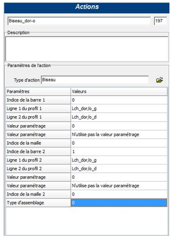
Assembly
- Definition : Bevel between two profiles (mitering)
The bevel action is an assembly action that allows to make bevels between two profiles.
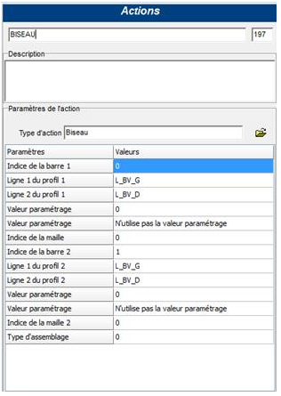
- Use case : Assembly procedure
- Parameters :
-
Index of Bar 1 : index of the first bar involved in the beveling action in the assembly node
-
Line 1 of profile 1 : first line to identify profile 1
-
Line 2 of profile 1 : second line to identify profile 1
-
Parameterization value : (Optional) Value to identify the profile defining the bevel line on bar 1
-
Parameterization value : If defined with the value 'use parameterization value' the previous parameter is taken into account to identify the reference profile on bar 1
-
Mesh index :
- Values:
- -1 if the profiles concerned by the action are extruded to the bar
- 0, 1, 2, 3, ... mesh index in the node if at least one of the profiles concerned by the action is extruded to the mesh
- Values:
-
Index of Bar 2 : index of the second bar affected by the bevel action in the node
-
Line 1 of profile 2 : first line to identify profile 2
-
Line 2 of profile 2 : second line to identify profile 2
-
Parameterization value : (Optional) Value to identify the profile defining the reference line on bar 2
-
Parameterization value : If defined with the value 'use parameterization value' the previous parameter is taken into account for identifying the reference profile on bar 2
-
Mesh index 2 :
- Values:
- -1 if the profiles concerned by the action are extruded to the bar
- 0, 1, 2, 3, ... mesh index in the node if at least one of the profiles concerned by the action is extruded to the mesh
- Values:
-
Type of assembly : defines whether the bevel is of the welding type (PVC profiles ) or not
- Values:
- 0 if the profiles concerned by the action are not welded (do not require extra length)
- 1 if the profiles concerned by the action are welded (require an extra length)
- Values:
-
Note: the number of the bars, on which the profiles that are to be bevelled are located, is visible in the preview of the respective assembly.
Note: The bevel action only concerns two profiles. If several profiles are to be beveled, several actions must be created (or a 'follow profile cutting planes' action must be used).
- Example : Case of a mitre-cut frame assembly T he assembly node is as follows:
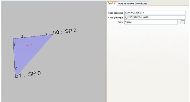
The assembly thus concerns 1 profile of bar 0 and bar 1
The corresponding assembly action is :
- Definition
- Use case
- Parameters
- Definition : abutment of a profile on another Assembly action allowing a profile to abut on the face of another; the face being defined by a line present on the section
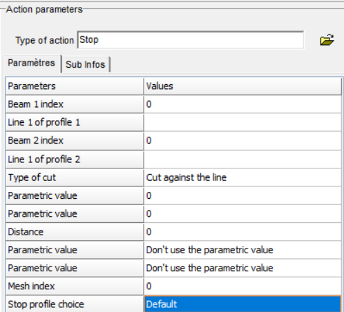
-
Use case : Assembly procedure
-
Parameters :
-
Index of bar 1 : index of the bar of the profile(s) to be abutted on the face of another in the assembly node
-
Line 1 of profile 1 : line allowing to identify the profile(s) of the IB1 bar to undergo the abutment action
-
Bar index 2 : index of the bar of the reference profile, on which the profile(s) of bar 1 must abut, in the assembly node
-
Line 1 of profile 2 : line on which the profile(s) of bar 1 must abut
-
Plane type : selection of the type of cutting plane resulting from the stop action
- Values:
- Cutting plane along the line:
- Perpendicular plane (first point of contact)
- Perpendicular plane (last point of contact)
- 45° point (plane and perpendicular profiles) : Note: used in the frame for the assembly of the crossbar on the frame in point.
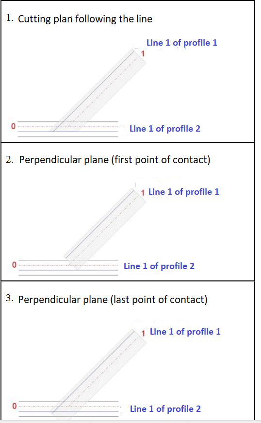
- Values:
-
Parameterization value : possibility to identify the profile(s) of bar 1 to undergo the action (in addition to the identification line) by specifying 'the parameterization value of the positioned profile action
-
Parameterization value : possibility to identify the profile of bar 2 serving as reference for the stop action (in addition to the stop line) by specifying the parameterization value of the positioned profile action
-
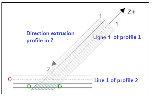
Distance : possibility to add an additional distance to the cutting plane from the stop. This is a distance normal to the profile section (distance in the profile extrusion frame). Example : when type of plane following the line and a negative Distance D :
-
Parameter value : This parameter specifies whether the parameter value specified above is used to identify the profile(s) of bar 1
- Values:
- Do not use the parameter value
- Uses parameter value
- Values:
-
Parameter value : This parameter specifies whether the parameter value specified above is used for the identification of the profile of bar 2
- Values :
- Do not use the parameter value
- Uses the parameter value
- Values :
-
Mesh index : Index of the mesh in the node
- Values:
-
from 0 to n.meshcount-1 : when one of the profiles concerned by the action is extruded on a mesh (in other words, in the positioned profile action, the "extrusion" parameter is mesh1 or mesh2) it is necessary to indicate on which mesh in the node the profile is located.
-
-1 : when the profiles concerned by the action are all extruded at the bar (no notion of mesh).
-
- Values:
- Note: Stop action:
Choice of profiles for the action according to the mesh index :
- Operating principle
- For the bar which undergoes the action (bar index1):
- If the mesh index = -1 The program scans the bar for profiles extruded on the bar and containing the line specified in the parameter.
- If the mesh index < > -1 The program scans the bar looking for profiles extruded at the mesh, whose index is specified in parameter, and at the bar, and which contain the line specified in parameter. All profiles found will be affected by the action
- For the bar containing the profile for the stop plane (bar index 2):
- If the mesh index = -1 The program scans the bar for a profile extruded to the bar and containing the line specified in the parameter. The program takes the first profile found (from parents to children)
- If the index of the mesh < > -1 The program scans the bar for a profile extruded to the mesh, whose index is specified in parameter, and which contains the line. the program takes the first profile found.If no mesh profile contains the line, the program scans the extruded profiles at the bar.
- For the bar which undergoes the action (bar index1):
- Operating principle
-
-
Example : Assembly of the transom on the frame
Assembly of the sash profile
in progress
Cutting against first line encountered
- Definition : abutment of one profile on another, following the first abutment line encountered. Action de butée permettant à un profil de buter sur la première ligne de butée rencontrée. L’action permet donc de travailler avec plusieurs lignes de butée présentes sur la barre 2.
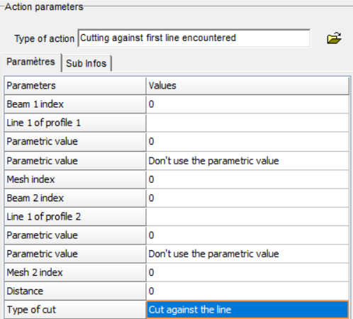
- Use case : Assembly procedure
- Parameters : The parameters are identical to the stop action.
see stop action
- Example: Assembly between crossbeams and posts Let's say a post profile that can be put in different orientations. The crossbeams between the posts must abut the post. Add the stop line on the section of the column profile at the different possible stop points:

The traverse profile (in gray) will abut the first line encountered, in the direction of the node.

If additional profiles can be hooked onto the A-post and receive the crossbar stop, the process can be continued by adding the stop line on the sections of these profiles:

Note:
The program will choose the first stop plane encountered by one of the four points of the profile's bounding box undergoing the cut.
Example : 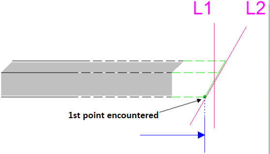
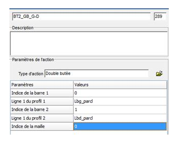
- Definition : abutment of two profiles between them
Action of assembling two profiles; the first one abuts on the second one and this last one abuts in its turn on the first one.
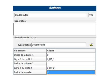
- Use case : Assembly procedure
- Parameters :
- Index of bar 1 : index of the bar in the node of the profile(s) to be abutted on the line Line 1 of profile 2 of a profile of bar 2
- Line 1 of profile 1 : abutting line of the profile(s) of bar 2
- Index of bar 2 : index of the bar in the node of the profile(s) to abut on the line Line 1 of profile 1 of bar 1
- Line 1 of profile 2 : abutting line of profile(s) of bar 1
- *Mesh index,: index of the mesh in the node
- Values:
-
from 0 to n.meshcount-1: when one of the profiles concerned by the action is extruded on a mesh (in other words, in the positioned profile action, the "extrusion" parameter is mesh side1 or mesh side2) it is necessary to indicate on which mesh in the node the profile is located (index of the mesh in the assembly node).
-
-1 : when the profiles concerned by the action are all extruded at the bar (no notion of mesh)
-
- Values:
- Example : Case Assembly of the glazing beads in double stop
The assembly node is as follows:
 The assembly thus concerns 1 profile of bar 0 and bar 1
The corresponding assembly action is :
- Definition : abutment of a profile on an accessory at the node
Note:
This action only works when the accessory to be bumped is placed at the assembly node
Assembly action allowing a profile to abut the face of an accessory at the node; the face being defined by a surface present on the 3D object of the accessory
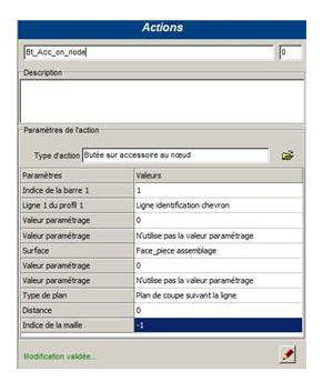
- Use case : Assembly procedure
- Parameters :
-
Index of bar 1 : index of the bar in the node of the profile(s) to abut the face of an accessory
-
Line 1 of profile 1 : line to identify the profile(s) of bar 1 to undergo the abutting action
- attention: the line must be extruded to the bar
-
Parameterization value : possibility to identify the profiles to be subjected to the action (in addition to the identification line) by specifying the parameterization value of their positioned profile action
-
Parameterization value : allows you to specify whether or not to use the parameterization value of the profile(s) of bar 1
-
Surface : Face on which the profile(s) of bar IB1 should abut.
- Note: Accessory identification This face is also used to identify the accessory which is at the node. If several accessories have the same face, it is necessary to use the parameter value of the accessory placement action at the node to identify the accessory on which you wish to make the stop.
See also : creating a surface : Add a surface in the 'Points-Lines-Surfaces' tool.
See also: defining a surface on a 3D object.
-
Parameterization value : possibility to identify the accessory on which the profile(s) of bar 1 must abut. this parameterization value is defined in the accessory placement action at the node.
-
Parameter value : allows to specify whether or not to use the parameter value of the accessory.
-
Plane type : selects the type of cutting plane resulting from the stop action
- Values:
- Cutting plane along the line:
- Perpendicular plane (first point of contact)
- Perpendicular plane (last point of contact)
- 45° point (plane and perpendicular profiles) :
- Note: used in the frame for the assembly of the crossbar on the frame in point.
- Values:
-
Distance : possibility to add an additional distance to the cutting plane from the stop. This is a distance normal to the profile section (distance in the profile extrusion mark). Identical to the distance in the stop action
-
Mesh index : Index of the mesh in the node.
- Values:
-
from 0 to n.meshcount-1: when one of the profiles concerned by the action is extruded on a mesh (in other words, in the positioned profile action, the "extrusion" parameter is mesh side1 or mesh side2) it is necessary to indicate on which mesh in the node the profile is located.
-
-1 : when the profiles concerned by the action are all extruded at the bar (no notion of mesh)
-
- Values:
-
- Definition : this action allows to extend one or more profiles at a node by means of a formula
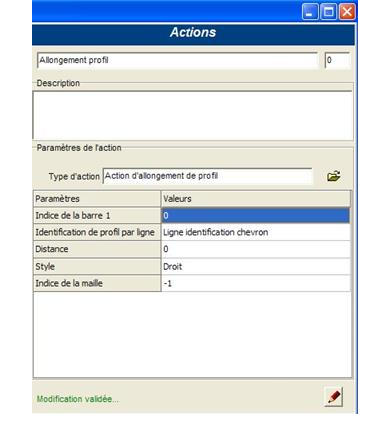
- Use case : Assembly procedure
- Parameters :
-
Index of bar 1 : index of the bar, in the assembly node, of the profile(s) to undergo elongation
-
Profile identification by line : line to identify the profile(s) of the IB1 bar to undergo the action
- attention: the line must be extruded to the bar
-
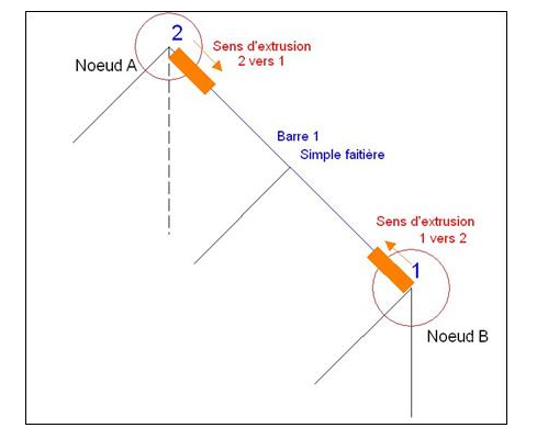
Distance : elongation formula. The positive direction is determined by the direction of the extrusion axis Z (positive from 2 to 1. A profile is always extruded in the negative Z (see extrusion of a profile))
- Note: In the distance of the stretch action, it is possible to use the variables of the
bar object of bar 1.
It is not mandatory to use a variable of the node object.
If I want a distance depending on the slope of the bar I can write either :
- b.slope
- n.vbeams(...).slope
- Note: In the distance of the stretch action, it is possible to use the variables of the
bar object of bar 1.
It is not mandatory to use a variable of the node object.
If I want a distance depending on the slope of the bar I can write either :
-
Style :
- Straight: the cutting plane of the profiles is perpendicular to the bar
- Vertical: the cutting plane of the profiles is a vertical plane
-
Mesh index : index of the mesh in the node
- Values:
- from 0 to n.meshcount-1: when one of the profiles concerned by the action is extruded on a mesh (in other words, in the positioned profile action, the "extrusion" parameter is mesh side1 or mesh side2) it is necessary to indicate on which mesh in the node the profile is located.
- -1 : when the profiles concerned by the action are all extruded at the bar (no notion of mesh)
- Execution of the procedures
- Bar index 1 : Bar index for the stop of profile 1
- Profile line 1 : Stop line of the first cut profile
- **Parameterization value : Parameterization value of the profile to be identified for the stop of the first profile
- Parameterization value : specifies whether the profile identification of bar 1 should take into account the parameterization value
- Mesh index : Mesh index of the first profile
- Bar index 2 : Bar index for the stop of profile 2
- Profile line 2 : Stop line of the second cut profile
- Parameterization value : Parameterization value of the profile to be identified for the stop of the second profile
- Parameterization value : specifies whether the profile identification of bar 2 should take into account the parameterization value
- Mesh index 2 : Mesh index of the second profile
- Values:
-
- Definition
- Use case
- Parameters
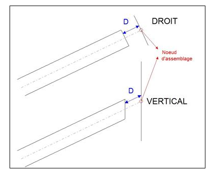
1-node profile cutting action with assembly line
- Definition : this action allows to extend one or more profiles at a node by means of a formula
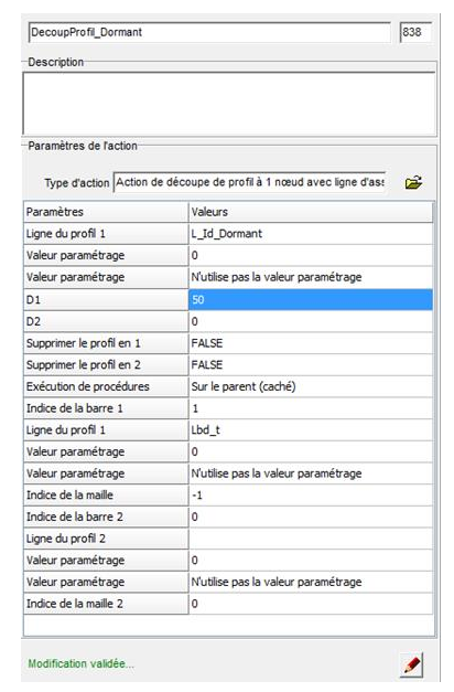
- Use case : Assembly procedure
- Parameters :
- Profile line 1 : line to identify the profile to be cut.
- Attention: Only one profile will be able to undergo the action. If several profiles contain this line, the program will only take into account the first one found.
- Parameterization value : Parameterization value of the profile to identify
- Parameterization value : Specify if the identification of the profile must take into account the parameterization value
- D1 : Complementary elongation value of the first profile from the cutting.
- D2 : Complementary elongation value of the second profile resulting from the cutting.
- Note: If no information is defined in bar1 and bar2, the additional elongation is done with respect to the node.
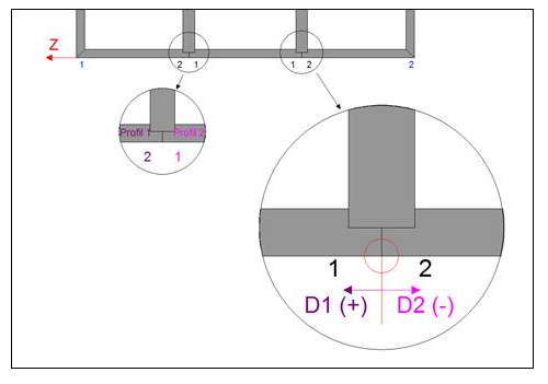
- Note: If no information is defined in bar1 and bar2, the additional elongation is done with respect to the node.
- Delete profile in 1 : Places a deletion information at the end 1 of the second profile
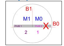
- Delete profile in 2 : Places a deletion information at the end 2 of the first profile
- Note: a profile has at each of its 2 ends, a deletion information, it is deleted.
- Profile line 1 : line to identify the profile to be cut.
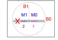
Targeted offset action on a point
- Definition : This action allows you to move a bar to a "target" point, defined around the node.
- Use case : Assembly procedure
- Parameters :
- Index of bar 1 : Index of the bar in the assembly node that is to be offset.
- Mesh index : mesh index of the bar 1 profile at the node ("-1" if the profile extruded to the bar).
- Profile point of bar 1 : Point of a profile that is on bar 1 (will be used as a "line of sight" for misalignment)
- Parameterization value : (Optional) Parameterization value of the profile
- Parameterization value : If defined with the value 'use parameterization value' the previous parameter is taken into account for the identification of the reference profile on bar 1
- Bar index 2 : Index of the bar, in the assembly node that will contain the point for the target definition.
- Mesh index : mesh index of the bar 2 profile at the node ("-1" if the profile is extruded to the bar)
- Point of bar 2 profile : Point of a profile that is on bar 2 for the target definition.
- Parameterization value : (Optional)Parameterization value of the profile
- Parameterization value : If defined with the value 'use parameterization value' the previous parameter is taken into account for the identification of the reference profile on bar 2
- Bar index 3 : Index of the bar, in the assembly node that will contain the line for the target definition.
- Mesh index : mesh index of the bar 3 profile at the node ("-1" if the profile extruded to the bar).
- Profile line of bar 3 : Line of a profile that is on bar 3 for the target definition.
- Parameterization value : (Optional) Parameterization value of the profile
- Parameterization value : If defined with the value 'use parameterization value' the previous parameter is taken into account for the identification of the reference profile on bar 3
- Explanation :
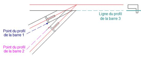
Definition of the target by the parameters of bars 2 and 3 :
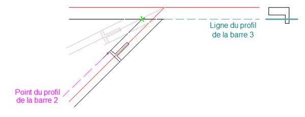
Definition of the line of sight by the parameters of bar 1, result:
Note: The offset does not apply to the bar itself.The wire volume is not modified, only the whole of the profiles of the bar is misaligned.
- Definition
- Use case
- Parameters
- Definition
- Use case
- Parameters
-
Definition : This action allows to make several cuts of a profile leading to a node. The principle of the action is similar to the stop action, but allows up to 10 different cutting planes.
-
Use case : Assembly procedure
-
Parameters :
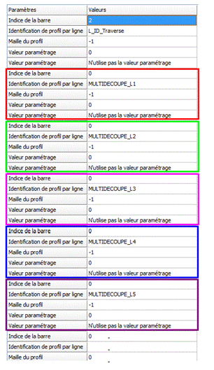 The first 5 parameters define the profile(s) receiving the cuts:
- Bar index : bar index of the profile(s) receiving the cuts
- Profile identification by line : Line allowing to identify the profile(s) of the bar to undergo the stop action
- Profile mesh : Mesh index of the considered profile
- Parameterization value : (Optional) Parameterization value of the profile
- Parameterization value : If defined with the value 'use parameterization value' the previous parameter is taken into account for the identification of the reference profile on bar 1 In groups of 5 parameters, the following fields define the different cuts of the profile to be made:
- Bar index : Index of the bar containing the profile that defines the cut via the line on its section
- Profile identification by line : Line on the section of a profile of the bar defining the cutting plane
- Profile mesh : Mesh index of the considered profile
- Parameterization value : (Optional) Parameterization value of the profile
- Parameterization value : If defined with the value 'use parameterization value' the previous parameter is taken into account for the identification of the reference profile on the bar The action allows to define up to 10 different cutting planes. Define the first n groupings of parameters required, leaving the next ones empty.
-
Explanation:
The "profile 1" assembly is calculated from projections of the section onto the different section planes. The lines defining the section planes can be placed on different profiles. The program calculates the "profile 1" connection in parts, starting from the origin of the section to the positive x and y of the section. Hence the importance of the order in which the lines are defined.
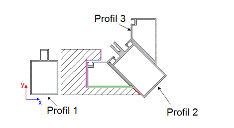
In this example, the cutting of the cross-section to be made - starting from the origin of the section towards the positive Ys - requires to assemble it against the cutting planes defined in the order by the lines: L1, L2, L3, L4 and L5 :
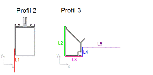
- Note: Unlike most assembly actions, for the multi-cut action the lengths of the lines (segments) are important in order to achieve the desired result.
- Definition
- Use case
- Parameters
Profile deletion action by a node
- Definition
- Use case
- Parameters
- Definition
- Use case
- Parameters
- Definition
- Use case
- Parameters
Follows the cutting plans of another profile
- Definition
- Use case
- Parameters
- Definition
- Use case
- Parameters
Filling
- Definition
- Use case
- Parameters
Cutting with distance and perpendicular to a bar
- Definition
- Use case
- Parameters
Cutting with distance and perpendicular to the bisector
- Definition
- Use case
- Parameters
Cutting on accessory face at the knot
- Definition
- Use case
- Parameters
- Definition : Allows you to cut a fill based on a line defined on a bar adjacent to the fill
- Use case : Assembly procedure
- Parameters :
- Bar index 1 : Index of the bar in the node supporting the cutting line
- Line 1 of profile 1 : Reference line for cutting
- Mesh index : Index of the mesh in the node that contains the fill to be cut
- Mesh index 2 : Index of the mesh in the node that will undergo the cutting The cut action on a profile line is placed in the procedure of an assembly node.
-
Definition : Allows you to cut the tip of a filling based on the cutting plane of another.
-
Use case : Assembly procedure
-
Parameters :
- Mesh index : Index of the mesh in the node that contains the fill to be cut
- Mesh index 2 : Index of the mesh that will serve as the cutting plane for the first mesh
- Bar index 1 : Index of the bar adjacent to mesh 2 to define the side of the reference mesh that will serve as the cutting plane for the first one The simple cut and fill action is part of the assembly node procedure.
-
Example: Cutting the tip of a filling in a veranda :
The mesh to be cut in the node is the index 0 mesh. The cutting of the tip of the filling will be based on a cutting plane of the mesh of index 1.
The index of the bar defines which side of the index 1 mesh will be used as a cutting plane for the cutting of the index 0 mesh.
In this case, it is the bar of index 2.
Action à paramétrer : 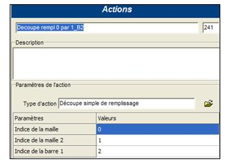
Résultat de l’action : 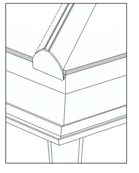
-
Definition : This action is used for positioning the layers of a multi-fill.
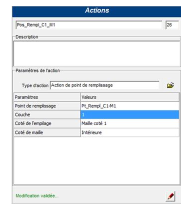
-
Use case : In the bar stacking procedure
-
Parameters :
- Fill point : user point for Z positioning and R indentation for the layer defined in the second parameter of the action
- Layer : index of the layer for which this action is set
- Attention:
- for multi-fill the layer indices start at 1. Layer 0 is the layer reserved for simple filling
- Attention:
- Stacking side : mesh side of the bar for which this action is set
- Mesh side: outer or inner : outer keeps an inner alignment with an extrusion of the fill to the outer / inner keeps an outer alignment with an extrusion of the fill to the inside
-
see Retract point
- Definition : Action permettant d’ajouter un retrait complémentaire
- in relation to the glazing points when positioning the infills in the meshes
- in relation to the structure attachment points when positioning a structure in another. Example : positioning of a frame in a veranda mesh
- Use case : Stacking procedure
- Parameters :
- X : value for the indentation of the filling or structure relative to the bar
Values:- positive value: enlarges the mesh (elongation)
- negative value: decreases the mesh (shrinkage)
- Y : value for the Z-displacement of the filling or structure with respect to the mesh
- Note 1: The removal is carried out in relation to the glazing or structure attachment points if the program finds them on the bar. If not, the removal action is performed in relation to the bar.
- Note 2: The removal actions are placed in :
- The mesh stacking procedure of the profile containing the glazing point for the infills
- The structure stacking procedure of the profile that contains the structure hooking point for a frame.
- X : value for the indentation of the filling or structure relative to the bar
- Definition : this action allows to fill a mesh by successive repetition of the extruded profiles
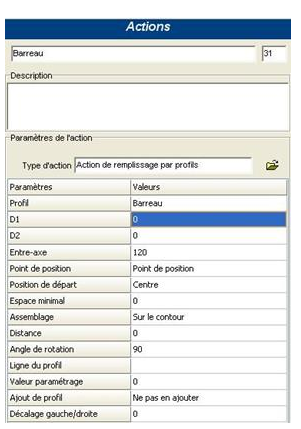
- Use case : Filling article by profiles
- Parameters :
-
Profile : selection of the item you want to extrude
-
D1 : not used at the moment
-
D2 : not used at the moment
-
Center distance : distance between the extrusion axes of the profile in the fill
-
Position point : Point defined on the profile section - corresponds to the position on the axis
-
Starting position : Defined way to calculate the distribution of the profiles in the mesh
- Left end
- Center
- Right end
-Note:
- In the Left End case: The distribution is calculated from the left of the fill, the residual of the profile distribution is on the right.
- In the Center case: The distribution is calculated from the center of the mesh, the residual of the profile distribution is identical on the left and right
- In the case of Right End: The distribution is calculated from the right of the filling, the residue of the distribution of profiles is on the left
- Minimum space : distance from the distribution residual for which a position for a new profile extrusion axis should not be calculated
- Remark: The minimum space should not be larger than the center-to-center distance
- Assembly : Defines the method of calculating the assembly on the edges of the mesh
- On the contour
- At the first point of contact
- At the last point of contact
- Distance : Offset distance from the start of the profile distribution calculation.
- Rotation angle : Value between 0° and 180° defining the extrusion angle of the profiles with respect to the horizontal 90° corresponds to the vertical
- Profile line(*) : Stop line (top) for the profiles in the filling. The stop line does not have to be defined on the bar that bounds the mesh containing the fill. The stop line will be searched in the direction 1 to 2. If no stop line is found, the boundary of the fill profiles is defined by the fill point per profile placed on the bar bounding the mesh containing the fill. If no filling point per profile is found, the mesh boundary corresponds to the profile boundary of the filling
-
Parameterization value : value characterizing the profile extruded by this action (value that can be tested in the procedures by p.value)
-
Add profile(*) : option to place an additional profile in the fill
- Do not add any
- To the left
- To the right
- Both sides
Remark:
The filling by profiles is defined on the principle of an ARM type division, the profiles are extruded along the axes resulting from this division.
If the mesh is divided into N, the result of this treatment will be the extrusion of N-1 profiles in the mesh. Depending on the type of filling processed, it is sometimes necessary to extrude N profiles into the mesh (Example: case of a filling by profiles whose slats are joined)
-
Left/right offset(*) : value to translate the fill per profile to the left (negative value) or to the right (positive value) (*) only available from version 2.0 Example : Case of a filling by profile defined from the variables of the article "filling by profile".
-
The profile is defined in a variable of type "list of articles", the other parameters are defined by the user (variables defined in the article of filling by profiles)
ATTENTION :
- The profile fill action does not create a bar - therefore it is not possible to extrude additional profiles using the stacking procedure associated with the bar/blade profile defined in the fill action. This stacking procedure can only be used to add items, accessories at the end of the profile, To place additional profiles, it is necessary to work with an additional profile filling action that will be used to place the profiles.
- in case of use of profile filling delimited by a line - the program searches for the line on all bars crossed by the filling profile and the calculation of intersection is performed at the first encountered occurrence of this line - it is therefore advisable to define this line on a dummy which can be placed on a profile stack according to user's choices.
- in the case of using a profile filling delimited by a line - the variables defined in the profile filling article are not necessarily accessible on the bar supporting the stop line of the filling (PF.variable_xxxx ) - However, some variables can be useful to define the exact position of the stop line (for example the choice of the decorative ends which cause a greater or lesser indentation with respect to the position defined by the user). It is therefore necessary to associate these variables to a location that is accessible by all parts of the parameterization (to the construction model of the frame or the sash) - which also implies that the information is identical on all parts of the gate that use this profile filling - regardless of the mesh that integrates this filling!
Surface definition point action
- Definition : Cuts fills on their sides at a defined angle. This action is placed in an assembly node.
- Use case : All structures
- Parameters
- Definition : Cuts fills on their sides at a defined angle. This action is placed in an assembly node.
- Use case : all structures
- Parameters
- Beam 1 index : index of the bar in the node carrying the cutting plan definition line
- Profile 1 line : cutting plan definition line
- Mesh index : index of the mesh in the node to which the action is to be applied
- Parametric value : Parameter setting value for the profile carrying the cutting plane definition line (optional)
- Parametric value : Allows the parameter value to be used or not
Accessories
- Definition : this action allows to place a 3D accessory in relation to one of the ends of a profile
- Use case : Stacking procedure
- Parameters :
- Article_Acc : choice of the accessory to be placed at the end of a profile (reference or 3D).
- PointPosition : point on which the origin of the accessory will be placed. This point must belong to the section that will stack the action.
- LP2 : choice of a line. The point of intersection between the line from the extrusion of the position point and the surface from the LP2 line will correctly position the origin of the object. The line must be on a profile of a bar adjacent to the one that stacks the prop.
- Endpoint : choice of endpoint: endpoint1, endpoint2, low endpoint, high endpoint, left endpoint, right endpoint.
- Note: The use of left, right, top and bottom is only possible in a Frame - Gate construction. The program then performs a comparison of the coordinates of the nodes for the determination of left, right, top and bottom.
- Note: In the case of an offset profile with length, one can only work in relation to the end 1 of the profile (because for this type of profile Node1=Node2) - for a positioning at the end 2, it is possible to use the expression p.length for the definition of the parameter DZ (Attention: positive/negative sign to respect the convention of extrusion of an offset profile with length)
- DX : displacement along the X axis
- DY : displacement along the Y axis
- DZ : displacement along the Z axis
- RX : rotation along the X axis
- RY : rotation along the Y axis
- RZ : rotation along the Z axis
- Definition
- Use case
- Parameters
Accessory placement action at the node
- Definition : this action allows you to place a 3D accessory or reference in an assembly node
- Use case : Assembly procedure
- Parameters :
- Item : Choice of accessory to be placed at the node (reference or 3D)
- Quantity : at least 1
- Bar index 1 : Identification of the reference bar for positioning the axes of the 3d object
- Profile point : point on a profile on which the accessory item's marker will be positioned.
- Bar index 2 : (Optional)
- Note: -1 by default (see below).
- Profile line : any line of a profile that is on the index bar 2 and that is used to determine the insertion point of the item
- DX : displacement relative to the point calculated along the X axis
- DY : displacement relative to the point calculated along the Y axis
- DZ : displacement relative to the point calculated along the Z axis
- RX : rotation with respect to the point calculated along the X axis
- RY : rotation with respect to the point calculated along the Y axis
- RZ : rotation with respect to the point calculated along the Z axis
- Conventions:

-
The x-axis of the article marker = the direction of bar 1 in the extrusion direction from 1 to 2
-
The XZ plane is a vertical plane
-
The origin of the item reference frame is positioned at the intersection of the point of the profile of bar 1 and : the profile line of bar 2 or of the end of the profile of bar 1 if no indication concerning the index of bar 2 and the line (value of the parameter index bar 2 = -1)
-
The displacements dx,dy,dz,rx,ry,rz are carried out in the reference frame positioned according to the previous conventions.
-
Note: If parameter index of bar 2 = -1, the insertion point of the item becomes the intersection of the profile point of bar 1 and its end plane.

-
Note: Orientation of the axes of the 3D object when the reference bar (bar 1) is a hip or column type bar:
- Case of a hip : The X axis goes in the direction of the bar,positive from 1 to 2
- Case of the post :
- The X axis goes in the direction of the bar, positive from 1 to 2.
- The Z axis is perpendicular to the mesh on side 1
- Case of a hip : The X axis goes in the direction of the bar,positive from 1 to 2
-
Action of placing an accessory on an accessory
- Definition
- Use case
- Parameters
- Beam 1 index : index of the bar in the node on which the cutting plane definition line is located
- Profile 1 line : cutting plan definition line
- Mesh index : mesh with the fill we want to cut out
- Parametric value : setting value for the profile carrying the cutting plan definition line (optional)
- Parametric value : allows you to define whether or not you wish to take the parameter value into account
- Definition : Fixed number uniformly distributed
The fixed repetition action allows a set number of accessories to be placed on a profile and evenly distributed along the length of the bar.
- Use case : Stacking procedure
- Parameters :
- Item : Item of the accessory type (reference or 3D).
- Position Point : point on the profile on which the accessory is positioned. In the case of a 3D accessory, it is the origin of the 3D object's reference frame that is positioned on this point.
The position point is a point belonging to the profile item that stacks the accessory. - Line 1 of profile 1 : choose a line.
The point of intersection between the line from the position point extrusion and the surface from the profile 1 line will define the end 1 of the length on which the accessories will be positioned. This line must be located on a profile of a bar adjacent to the one that stacks the accessory. This parameter is optional (in this case starting point of the distance for positioning the accessories = end 1 of the profile). - Line 2 of profile 2 : same as line 1.
- End : not used
- DX : displacement of the accessories along the X axis (of the 3D object frame).
- DY : movement of the accessories along the Y axis (of the 3D object frame)
- DZ : movement of the accessories along the Z axis (of the 3D object frame)
- RX : rotation of the accessories along the X axis (of the 3D object frame)
- RY : rotation of the props along the Y axis (of the 3D object frame)
- RZ : rotation of the accessories along the Z axis (of the 3D object frame)
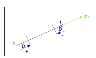
- D1 : Distance from endpoint 1from which the distance calculation for accessory placement is performed.
- D2 : Distance from endpoint 2 from which the distance calculation for accessory placement is performed.
- N : Fixed number of accessories.
- Values:
- Positive number: an accessory is placed at each end (minimum of two accessories).
- Negative number: the program does not place an accessory at ends 1 and 2
- Values:
- Definition : Uniformly distributed variable number
- Use case : Stacking procedure
- Parameters :
- Item : Item of the accessory type (reference or 3D).
- Position Point : point on the profile on which the accessory is positioned. In the case of a 3D accessory, it is the origin of the 3D object's reference frame that is positioned on this point.
The position point is a point belonging to the profile item that stacks the accessory. - Line 1 of profile 1 : choose a line.
The point of intersection between the line from the position point extrusion and the surface from the profile 1 line will define the end 1 of the length on which the accessories will be positioned. This line must be located on a profile of a bar adjacent to the one that stacks the accessory. This parameter is optional (in this case starting point of the distance for positioning the accessories = end 1 of the profile). - Line 2 of profile 2 : same as line 1.
- End : not used
- DX : displacement of the accessories along the X axis (of the 3D object frame).
- DY : movement of the accessories along the Y axis (of the 3D object frame)
- DZ : movement of the accessories along the Z axis (of the 3D object frame)
- RX : rotation of the accessories along the X axis (of the 3D object frame)
- *RY : rotation of the props along the Y axis (of the 3D object frame)
- RZ : rotation of the accessories along the Z axis (of the 3D object frame)
- D1 : Distance from endpoint 1 from which the distance calculation for accessory placement is performed.
- Remark : Distance D1or D2 : positive or negative ?
The positive or negative direction of the distance is defined by the extrusion mark of the
profile:
- Positive distance: distance in the Z +.
- Negative distance: distance in the Z -. In the diagram above, D1 is negative and D2 positive
- Remark : Distance D1or D2 : positive or negative ?
The positive or negative direction of the distance is defined by the extrusion mark of the
profile:
- D2 : Distance from end 2 from which the calculation of the distance for the placement of the accessories takes place (See note parameter D1).
- Maximum pitch : maximum/minimum distance between two accessories.
Values:
- positive value: maximum pitch (minimum two accessories)
- negative value: minimum pitch (accessory dimensions)
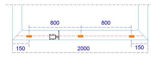
- Example1: Maximum pitch: Let's take a fixed profile, on which we want to place the water flow caps:
Let the frame profile and the water drainage cap be:
 Here is the situation to be respected: 1 cap per meter with an indentation to the left and right of the frame of 150 mm.
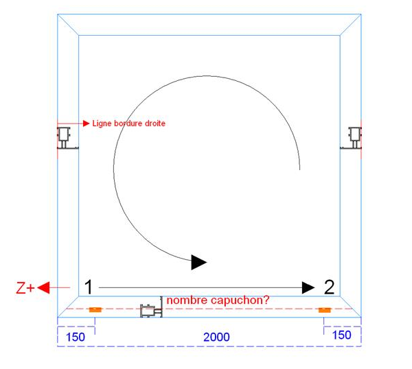
- Action parameters:
- Item : water drainage cap.
- Position point : Cap hanging point
- Line 1 profile 1 : Straight edge line
- Line 1 profile 2 : Straight edge line
- D1 : -150 (positive Z axis in the opposite direction to the extrusion)
- D2 : 150
- Maximum pitch : 1000 In the example,
- the total length of the bar 2000
- the length for the calculation of the accessories is Lacc
- Lacc : 2000 - (150*2) = 1700
- Lacc/maximum step = 1700/1000 = 1.7 = number of whole steps: 2
- Note: maximum pitch therefore rounded up to the unit
The real step between accessories is therefore 1700/2 = 850
Verification : 850 < 1000 (maximum pitch) : OK
Result : 3 accessories 850 mm apart
- Action parameters:
- Example 2: Minimum step: Positioning of accessories on the double ridge of the veranda: placement of ridges at regular intervals
- Action parameters:
- Item : peak
- Position point : ridge hook point
- Line 1 profile 1 : 'empty'
- Line 1 profile 2 : 'empty'
- D1 : -250
- D2 : 250
- Maximum pitch : - 500 (fixture footprint 500 mm)
The value is negative: corresponds to a minimum distance
E.g.: Length of the bar: 2200
- The length for the calculation of the accessories is Lacc
- Lacc = 2200- (2*250) = 1700
- Lacc/maximum step = 1700/500 = 3.4 = number of whole steps = 3
- Note: minimum pitch therefore rounded down to the unit The real pitch between accessories is therefore 1700/3 = 556 mm Verification : 556 > 500 (minimum pitch) : OK either : Length of the bar: 1400
- The length for the calculation of the accessories is Lacc
- Lacc = 1400- (2*250) = 900
- Lacc/maximum step = 900/500 = 1.8 = number of whole steps = 1
- Remark : minimum pitch thus rounded down to the unit
The real pitch between accessories is therefore 900/1 = 900 mm
Verification : 900 > 500 (minimum pitch) : OK
In this case, only 1 step : no accessory between D1 and D2 (only 1 at each end)
either: Length of the bar : 900 - The length for the calculation of the accessories is Lacc
- Lacc = 900- (2*250) = 400
- Lacc/maximum step = 400/500 = 0.8 = number of whole steps = 0
- Remark : minimum step so rounded down to the unit Lacc < minimum step and L > minimum step The program no longer takes into account D1 and D2 and places an accessory in the center of L. either : Length of the bar : 400
- The length for the calculation of the accessories is Lacc
- Lacc = 400- (2*250) = -100
- Lacc < minimum pitch and L < minimum pitch In this case, no accessory
- Action parameters:
Placement of an accessory at a caesura
- Definition : this action allows to place an accessory on a profile when a cut is made on this same profile
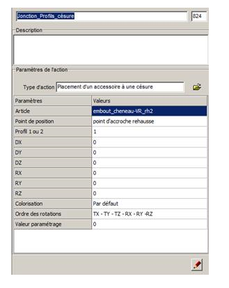
- Use case : Hyphenation procedure (linked to an article)
- Parameters :
- Item : Choice of the accessory to be placed at the caesura (reference or 3D).
- Position point : point on which the origin of the accessory will be placed. This point must belong to the section that will stack the action.
- Profile 1 or 2 : as a result of the hyphenation, the profile now consists of two pieces. The numbering of the profiles is done in the direction of extrusion of the bar and starts at 1
- Values:
- 1: Profile 1
- 2: Profile 2
- Note: The parameter is an expression whose result must return the value 1 or 2
- Values:
- DX : displacement relative to the point calculated along the X axis
- DY : displacement relative to the point calculated along the Y axis
- DZ : displacement relative to the point calculated along the Z axis
- RX : rotation with respect to the point calculated along the X axis
- RY : rotation with respect to the point calculated along the Y axis
- RZ : rotation with respect to the point calculated along the Z axis
- Colorization
- Rotation order
- *Parameterization value : assignment of a parameterization value for subsequent identification of the accessory
- Conventions :
- Additional variables for positioning :
For the positioning of the accessory, two additional variables exist as a result of the bisection:
- Z: distance between the end 1 profile and the bisection plane
- Thickness : thickness of the cut
- Accessory marker:
The positioning of the accessory marker follows the profile extrusion marker (in negative z). The positioning is thus similar to a prop on the end of the profile
The program positions the origin of the axes of the 3d object at the intersection of the position point of the profile and the caesura plane.
- If profile 1: origin of the accessory's reference frame at the intersection of the position point and the kerf plane
- § If profile 2 : origin of the accessory at the intersection of the position point and the thickness plane of the caesura plane
- If profile 1: origin of the accessory's reference frame at the intersection of the position point and the kerf plane
- Additional variables for positioning :
For the positioning of the accessory, two additional variables exist as a result of the bisection:
Hardware
Placement of hardware on top of hardware
- Definition
- Use case
- Parameters
- Definition
- Use case
- Parameters
- Definition
- Use case
- Parameters
Hardware with fixed repetition
- Definition
- Use case
- Parameters
Hardware with variable repetition
- Definition
- Use case
- Parameters
Colors
- Definition
- Use case
- Parameters
- Definition
- Use case
- Parameters
Colouring action (single colour)
- Definition
- Use case
- Parameters
Wired
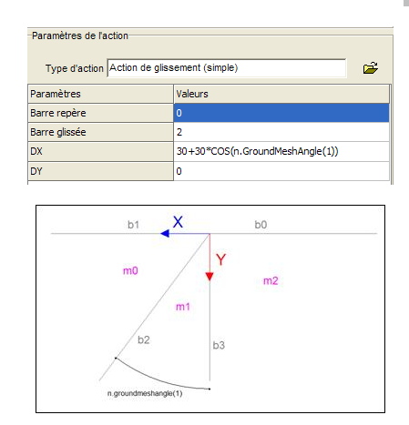
- Definition : Allows dragging a bar to the node
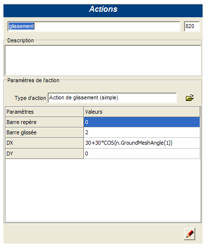
- Use case : Assembly procedure
- Parameters :
- Marker bar : reference bar in the node to position the X and Y axes for sliding the slider bar
- Slider bar : bar that will be slid
- DX : value of the bar slip in X
- DY : value of the bar slip in Y
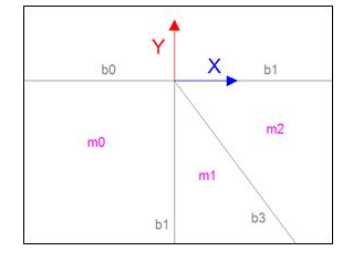
- Determination of X and Y values: Placement of the xy axis system
The X and Y slip values are ground values (veranda seen from above)
- X axis :
- The direction of the axis is defined by the direction of the reference bar
- The direction is positive towards the outside: opposite to the direction towards the other node of the bar
- Y axis : Direction and sense according to the X axis (reminder: right hand rule)
Example: Let's take the case of a veranda against a wall with a slope
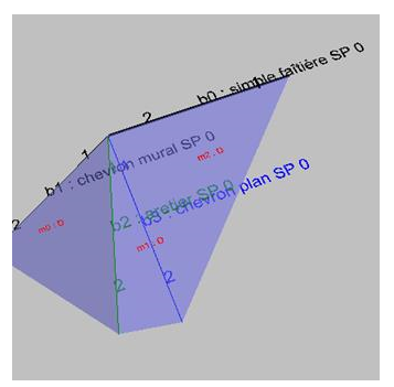
- X axis :
In this example, the index bar 2 will slide into the plane of mesh 1.
The mesh of index m0 will be recalculated while m1 and m2 will keep the original properties.
In the case where the reference bar is b1, the bar b2 slides in the plane of mesh 0.
Remark:
Let's look at the placement of the axes in the symmetrical node if the landmark bar remains the simple ridge:
Survey action (Construction 3d)
- Definition
- Use case
- Parameters
- Definition :
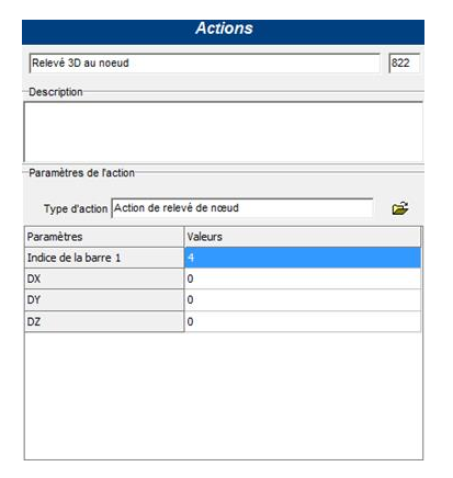
- Use case : Procedure for measuring the knot: Veranda - Manufacturing mode: Allows you to measure a radiating knot in order to respect the desired dimension of the wire (underneath the plate, or out of all profiles and accessories, ...)
- Parameters :
- Bar index1 : index of the reference bar in the node used to position the X and Y and Z axes for the survey
- DX : value of the survey in X
- DY : value of the survey in Y
- DZ : value of the reading in Z
- Determination of X, Y and Z values : The survey marker follows the same marker as the profile extrusion on the index bar1
Example: In the case below, the index parameter of bar 1 is bar 4
- Definition: this action defines the position of the leaf in the parent structure - dynamic opening process
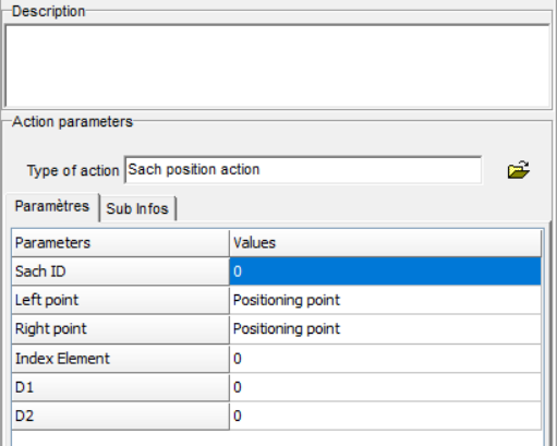
- Use case: dynamic opening process
- Parameters:
- Sash ID: Reference leaf index for defining the position
- Left point: Reference point, on the parent bar, for positioning the leaf to the left of this bar
- Right point: Reference point, on the parent bar, for positioning the leaf to the right of this bar
- Index Element: Parameterisation value - defined by the parameteriser
- D1: Offset value of the opening bar in relation to the uniform division of the parent mesh into N leaves - dimension 1 - see definition of A1 for "standard" opening processes
- D2: offset value of the opening bar with respect to the uniform division of the parent mesh into N leaves - side 2 - see definition of A2 for "standard" opening procedures
since 2.1
Hardware property definition action
- Definition: this action allows you to define the hardware properties on the dynamic openings
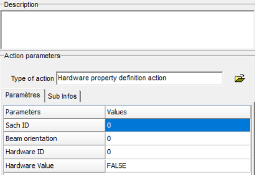
- Use case: dynamic opening process
- Parameters:
- Sash ID: Reference leaf index for the definition of the hardware property
- Beam orientation: Orientation of the reference bar in the sash for the definition of the hardware property:
- Hardware ID: Constant defining the type of hardware concerned by the action
| FR | EN | Constant | Value |
|---|---|---|---|
| POIGNEE | HANDLE | CG_CST_HANDLE | 1 (20) |
| PAUMELLE | HINGE | CG_CST_HINGE | 2 (21) |
| SERRURE | LOCK | CG_CST_LOCK | 4 (22) |
| GACHE | LOCKINGPLATE | CG_CST_LOCKINGPLATE | 8 (23) |
| ROULETTE | ROLLER | CG_CST_ROLLER | 16 (24) |
| HAUT | TOP | CG_CST_TOP | 32 (25) |
| BAS | BOTTOM | CG_CST_BOTTOM | 64 (26) |
| DROITE | RIGHT | CG_CST_RIGHT | 128 (27) |
| GAUCHE | LEFT | CG_CST_LEFT | 256 (28) |
| BATTEMENT | MIDDLECONNECTION | CG_CST_MIDDLECONNECTION | 512 (29) |
| CHICANE1 | INTERLOCK1 | CG_CST_INTERLOCK1 | 1024 (210) |
| CHICANE2 | INTERLOCK2 | CG_CST_INTERLOCK2 | 2048 (211) |
| VERROU | BOLT | CG_CST_BOLT | 4096 (212) |
| TRINGLE | ROD | CG_CST_ROD | 8192 (213) |
| COMPAS | COMPASS | CG_CST_COMPASS | 16384 (214) |
- Hardware Value: Boolean TRUE/FALSE - to enable or disable a hardware property
since 2.1
Action to define the number of leaves per mesh
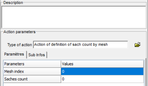
- Definition:this action defines the number of leaves on a mesh - dynamic opening process
- Use case: dynamic opening process
- Parameters
- Mesh index: Index of the mesh for which the number of leaves is defined
- Saches count: Number of leaves in the mesh.
since 2.1
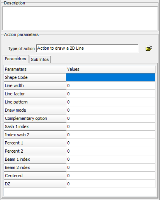
- Definition: this action allows to define a representation line of the opening symbol - dynamic opening process
- Use case: dynamic opening process
- Parameters
- Shape code: Information to determine the compatible shape for the opening process
- rectangle: 1_RDRHRGRB
- Line width: value defining the thickness of the line drawing
- Note: In the "Standard" opening procedures, the symbols are drawn with a line width = 2
- Line factor: value defining the drawing line of the line
- Note: In the "Standard" opening processes,
- Solid line (opening to the user in the active view): Line factor = 0
- Dotted line (opening from the user in the active view): Line factor = 6
- Note: In the "Standard" opening processes,
- Line patern: value defining the line type of the line
- Note: In the "Standard" opening processes,
- Solid line (opening to the user in the active view): Line pattern = 0
- Dotted line (opening from the user in the active view): Line pattern = 43690
- Note: In the "Standard" opening processes,
- Draw mode: Definition of the type of view in which the symbol will be visible
- 1 = European Standard - External View
- 2 = European Standard - Interior View
- 3 = European Standard - Top view
- Complementary option: Definition of the design at the ends of the line
- 1 = Arrow at end 1 and end 2
- 2 = Arrow at end 1
- 3 = Arrow at end 2
- 4 = No arrow
- Sash 1 index: Start leaf index of the line Value: >=0
- Index sash 2: End leaf index of the line Value: >=0
- Percent 1: Position on the bar at the beginning of the line: [0;100]
- Percent 2: Position on the bar of the end of the line Value: [0;100]
- Beam 1 index: Index of the bar, in the starting leaf of the symbol, at the beginning of the line Value: >=0
- Beam 2 index: Indice de la barre, dans le vantail de fin du symbole, de fin de la ligne Valeur : >=0
- Centered:
- DZ:
- Shape code: Information to determine the compatible shape for the opening process
since 2.1
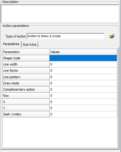
- Definition: this action allows to define a representation line of the opening symbol - dynamic opening process
- Use case: dynamic opening process
- Parameters
- Shape code: Information to determine the compatible shape for the opening process
- rectangle: 1_RDRHRGRB
- Line width: value defining the thickness of the line drawing
- Note: In the "Standard" opening procedures, the symbols are drawn with a line width = 2
- Line factor: value defining the drawing line of the line
- Note: In the "Standard" opening processes,
- Solid line (opening to the user in the active view): Line factor = 0
- Dotted line (opening from the user in the active view): Line factor = 6
- Note: In the "Standard" opening processes,
- Line patern: value defining the line type of the line
- Note: In the "Standard" opening processes,
- Solid line (opening to the user in the active view): Line pattern = 0
- Dotted line (opening from the user in the active view): Line pattern = 43690
- Note: In the "Standard" opening processes,
- Draw mode: Definition of the type of view in which the symbol will be visible
- 1 = European Standard - External View
- 2 = European Standard - Interior View
- 3 = European Standard - Top view
- Complementary option: Definition of the design at the ends of the line
- 1 = Arrow at end 1 and end 2
- 2 = Arrow at end 1
- 3 = Arrow at end 2
- 4 = No arrow
- Ray: Value or expression defining the radius of the cross (or circle) drawing circle
- X: Value or expression defining the position in X of the centre of the circle
- Y: Value or expression defining the Y position of the centre of the circle
- Sash 1 index: Leaf index in which the symbol will be drawn
- Shape code: Information to determine the compatible shape for the opening process
since 2.1
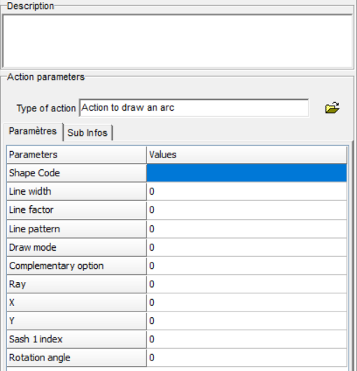
- Definition: this action allows to define a representation line of the opening symbol - dynamic opening process
- Use case: dynamic opening process
- Parameters
- Shape code: Information to determine the compatible shape for the opening process
- rectangle: 1_RDRHRGRB
- Line width: value defining the thickness of the line drawing
- Note: In the "Standard" opening procedures, the symbols are drawn with a line width = 2
- Line factor: value defining the drawing line of the line
- Note: In the "Standard" opening processes,
- Solid line (opening to the user in the active view): Line factor = 0
- Dotted line (opening from the user in the active view): Line factor = 6
- Note: In the "Standard" opening processes,
- Line patern: value defining the line type of the line
- Note: In the "Standard" opening processes,
- Solid line (opening to the user in the active view): Line pattern = 0
- Dotted line (opening from the user in the active view): Line pattern = 43690
- Note: In the "Standard" opening processes,
- Draw mode: Definition of the type of view in which the symbol will be visible
- 1 = European Standard - External View
- 2 = European Standard - Interior View
- 3 = European Standard - Top view
- Complementary option: Definition of the design at the ends of the line
- 1 = Arrow at end 1 and end 2
- 2 = Arrow at end 1
- 3 = Arrow at end 2
- 4 = No arrow
- 5 = Full
- Ray: Value or expression defining the radius of the cross (or circle) drawing circle
- X: Value or expression defining the position in X of the centre of the circle
- Y: Value or expression defining the Y position of the centre of the circle
- Sash 1 index: Leaf index in which the symbol will be drawn
- Rotation angle: Value or expression defining the value of the angle to be drawn
- Shape code: Information to determine the compatible shape for the opening process
since 2.1
Machining
Machining action on profile end
- Definition
- Use case
- Parameters
- Definition
- Use case
- Parameters
- Definition : this action allows to place a machining in an assembly node
- Use case : Assembly procedure
- Parameters :
- Machining : Selection of the machining to be placed at the node
- Bar index 1 : Identification in the node of the reference bar for positioning the machining
- Value: >=0
- Profile point : Point of a profile on which the machining marker will be positioned.
- Parameterization value : (Optional) Value that can be used to identify the profile that defines the reference point on bar 1
- Parameterization value : If defined with the value 'use parameterization value' the previous parameter is taken into account for the identification of the profile that will support the machining
- Index of bar 2 : (Optional)
- Default value: -1
- Convention: see below
- Profile line : (Optional) Possible line of a profile located on the bar of index 2 and allowing to determine the insertion point with the point of bar 1 to create the machining marker.
- Parameterization value : (Optional) Value that may be used to identify the profile defining the reference line on bar 2.
- parameterization value : If defined with the value 'use parameterization value' the previous parameter is taken into account for the identification of the reference profile on bar 2
- Index of bar 3 : Identification of the bar in the reference node of the machined profile
- Value: >=0
- Identifying line of the machined profile : Line of a profile that is on the bar with index 3 undergoing machining.
- Parameterization value : (Optional) Value that can be used to identify the profile undergoing machining on the index bar 3.
- Parameterization value : If defined with the value 'use parameterization value' the previous parameter is taken into account for the identification of the reference profile on bar 3
- DZ : displacement relative to the calculated point along the Z axis.
- Additional value : not used
- Conventions :

- The x-axis of the article marker = the direction of bar 1 in the extrusion direction from 1 to 2
- The XZ plane is a vertical plane
- The origin of the item reference frame is positioned at the intersection of the point of the profile of bar 1 and : the profile line of bar 2 or of the end of the bar 1 profile if no indication concerning the bar 2 index and the line (value of the bar 2 index parameter = -1)
- Positioning in dz is performed in the marker positioned according to the previous conventions.
Note: If parameter index of bar 2 = -1, the insertion point of the item becomes the intersection of the profile point of bar 1 and its end plane.

- Availability/Updates : V2.0.1.131
Machining action with fixed repetition
- Definition
- Use case
- Parameters
Machining action with variable repetition
- Definition
- Use case
- Parameters
Placement of a machining at a caesura
- Definition
- Use case
- Parameters
Quotation
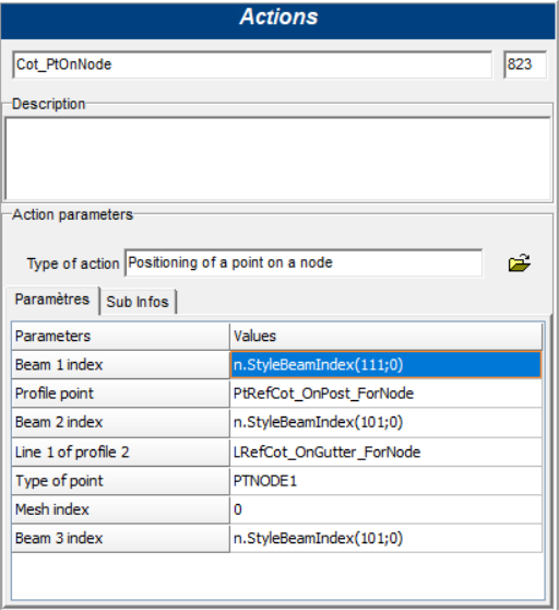
Point definition action at the node
- Definition : The purpose of this action is to position a reference point in 3d. This point will be positioned at the intersection of the line coming from the point of the index bar1 and the plane coming from the line of the index bar 2
-
Use case : Dimension point procedure (linked to an assembly node)
-
Parameters:
-
Bar index 1: Index of the bar, in the assembly node, of which one of the points of a profile will be used as reference for the calculation of the 3d point
-
Profile point: point which will be projected on the plane defined by the line of bar 2 for the calculation of the 3d point positioning
-
Index of bar 2 : Index of the bar, in the assembly node, of which one of the lines of a profile will be used as reference for the 3d reference point calculation
-
Line 1 of profile 2: line from which a plane will be generated for the calculation of the 3d reference point positioning
-
Type of dimensioning point: Name of the reference point which will be generated following the intersection of the line resulting from the point of the index bar 1 and the plane resulting from the line of the index bar 2
Note: The parameter Type of dimensioning point must be entered manually. The text does not have to be translated, so it is not necessary to use the text tool
-
Mesh index: This parameter is not used at the moment
-
Bar index 3: Index of the bar, in the assembly node, which will be used as reference for the dimension line.
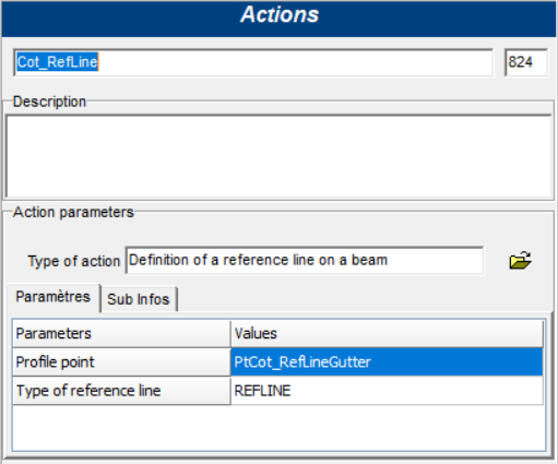
Bar reference line definition action
- Definition : The purpose of this action is to define the position of the dimension that will be generated.
The position will be specified by means of a point that the program will find on one of the profiles of the bar stack
-
Use case : Reference line procedure (linked to a bar stack)
-
Parameters
-
Profile point: point which will be projected on the plane defined by the line of bar 2 for the calculation of the 3d point position
-
Reference line type: name of the reference line that will be generated following the extrusion of the point for the position of the dimension
Note: The parameter Reference line type has to be entered manually. The text does not have to be translated, so it is not necessary to use the text tool
-
Definition :
-
Use case
-
Parameters
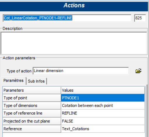
- Definition
- Use case : Procedure for defining a quotation (linked to an automatic view)
-
Parameters :
-
Type of dimensioning point: name of the type of dimensioning point (this point is filled in the type action "Action of defining point at node")
-
Type of dimensioning :
-
Cotation between each point: connects all the points of the type entered on the same dimension
-
Cotation between extremities: connects the first and last points of the given type
-
Scale cotation: connects the first point and the next one successively on different dimensions
-
-
Type of reference line: name of the reference line which will be used to position the dimension (this line is entered in the action of type "Action for defining a reference line at the bar")
-
Projected on the dimension plane: False or True: should the linear dimension be projected on the plane of the automatic view (see definition of an automatic view)
Example: (Type of plane in the view: ground plane)
- Reference: text of the quotation: this text will be visible to the user. It is therefore necessary to use the text tool
Note: Displaying the text of the rating :
To display the dimension calculated by the program, simply enter the characters: %f This value displays the rating with 2 digits after the decimal point
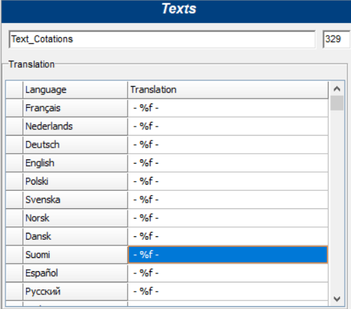
Other possible manipulation: %7.0f: 7 digits before the decimal point and 0 after
Dimensioning action perpendicular to the reference plane
- Definition : This type of dimension is defined by means of an action of type "Dimension action perpendicular to the reference plane" which is associated with an automatic view thanks to a procedure of type "Dimension definition procedure".
This action is used to generate in a 2d or 3d view a dimension perpendicular to a reference plane on the basis of the reference points that have been defined at the nodes (see Step 1)
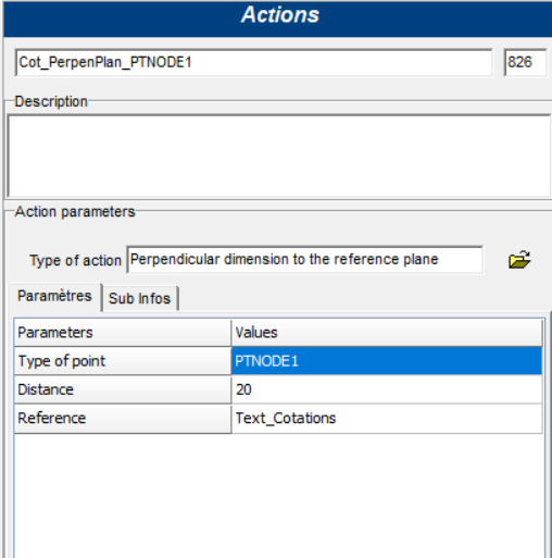
- Use case : Procedure for defining a quotation (linked to an automatic view)
- Parameters
- Type of dimensioning point: Name of the type of dimensioning point (this point is filled in the action of type "Point definition action at node")
- Distance: distance of the dimension from the point of measurement
- Note distance parameter: Display of the dimension
- In a 2D view
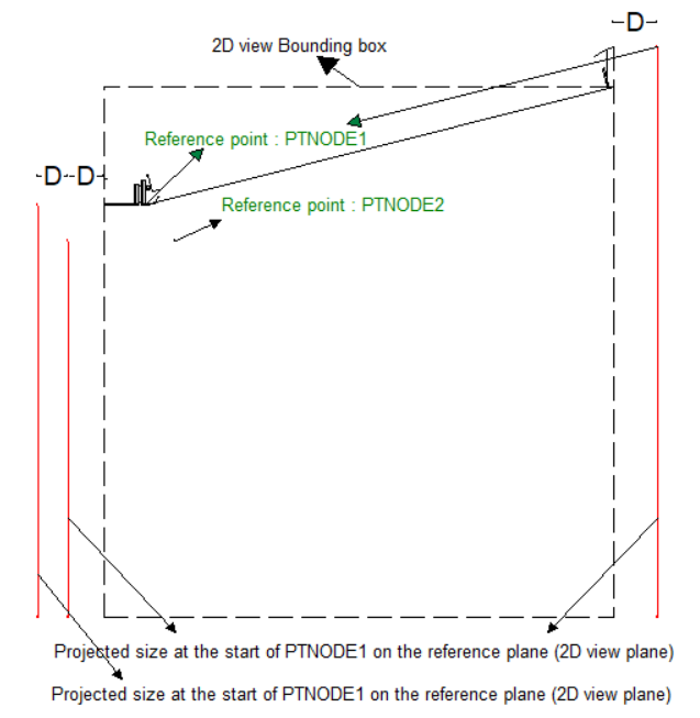
-
Value "D" is defined by the "Distance" value of the first action of this type found in the procedure
-
The order of the ratings is given by the order of the actions in the procedure
-
The first dimension is defined as the value D (Distance) from the bounding box in view 2d
-
A + distance places the dimension outside the bounding box while a - value places it inside
-
If the reference point is to the left of the middle of the dimension box, the dimension will be drawn to the left and vice versa
-
In a 3D view
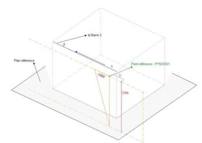
- The dimension is drawn in a plane defined by: the reference point (PTNODE1), a point at a distance of 1000 along the direction of the bar IB3 (Reference point action) and passing through the reference point and point projected on the reference plane (automatic view parameter)
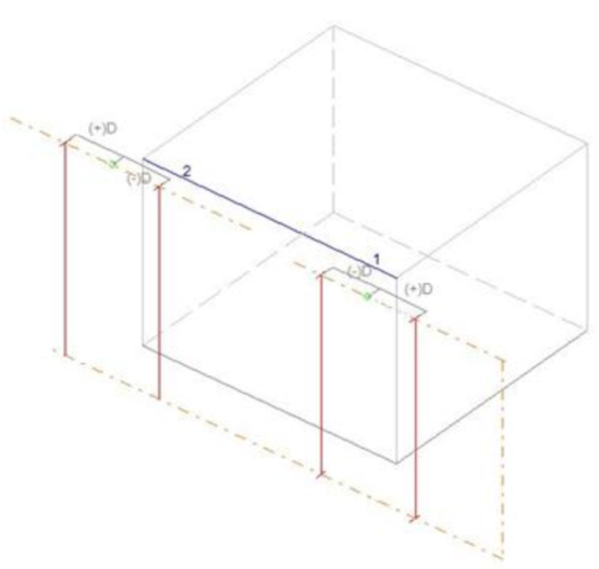
-
A distance with a + direction is drawn on the outside of the dimension box, while a - distance is drawn on the inside. If the reference point is closer to the end 1 of the bar IB3, the dimension will be drawn on side 1 of the bar and vice versa
- Reference: text of the quotation: this text will be visible to the user. It is therefore necessary to use the text tool
To display the dimension calculated by the program, simply enter the characters: %f This value displays the rating with 2 digits after the decimal point
Other possible manipulation: %7.0f: 7 digits before the decimal point and 0 after
- Definition
- Use case
- Parameters
- Parameter in quotation actions
- Value
- 0 or NoLine : no Leader line
- -1 or UntilPoint : Leader line starting from the dimension at the reference point.
- other value : size define in mm
- Example
- UntilPoint = 100%
- UntilPoint/10 = 10%
- -1 = 100%
- -5 = 500%
- -0.1 = 10
- Value