This section concerns : The predefinition of automatic views and dimensions of a construction
In 2.0, the parameterized views are accessible via the menu Database/Suppliers/Automatic views.
This mechanism no longer exists in version 2.1, the information is still visible to know what was set up in 2.0 but is no longer operational.
The designer must now define a procedure of type "Document procedure" and add actions of type "Action of parameterised views". This procedure must then be linked to the construction model on which the designer wishes to calculate his views.
All the views will then be pre-calculated during the dressing process. Another consequence of this new feature is the technical view frame in which the views are presented. They will now be directly accessible (all of them) and this justifies the disappearance of the view choice window and the menu asking you to generate them.
As the import is not automatic, the old menu still exists in order to easily carry out a manual migration of its views.
Veranda type construction
Definition of dimensioning points at nodes
Definition of the reference lines to the bars
Creation of dimensions based on points and lines
Linear dimensioning
Dimensioning perpendicular to a plane
Definition of dimensioning points at nodes
This step will define a series of 3D points from which dimension lines will be generated.
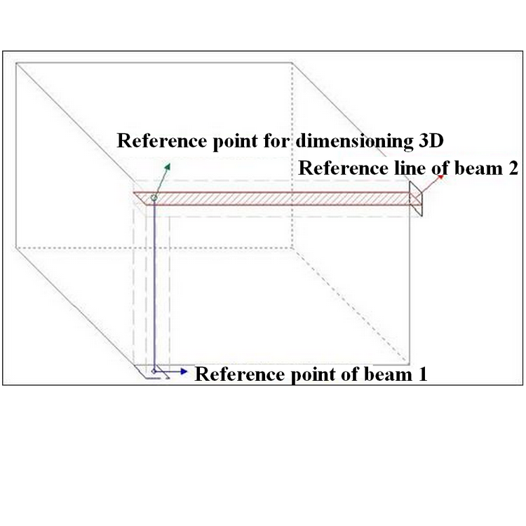
This information is defined by means of an action of type "Node point definition action" which will be associated with the assembly node(s) thanks to a procedure of type "Dimension point procedure".
- Step 1 : Point definition action at the node
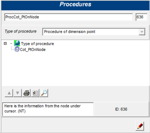
- Step 2 : Creation of the rating procedure
Put the point definition action at the node in a dimension point procedure
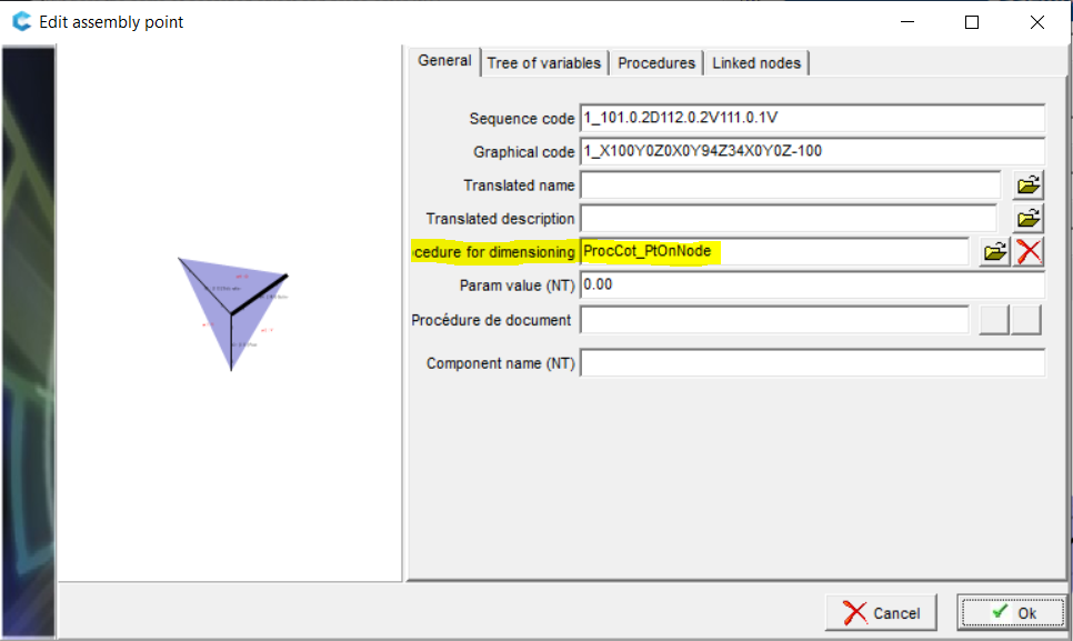
- Step 3 : Association of the procedure with the assembly node(s)
Associer la procédure de type point de cotation dans les nœuds d’assemblage
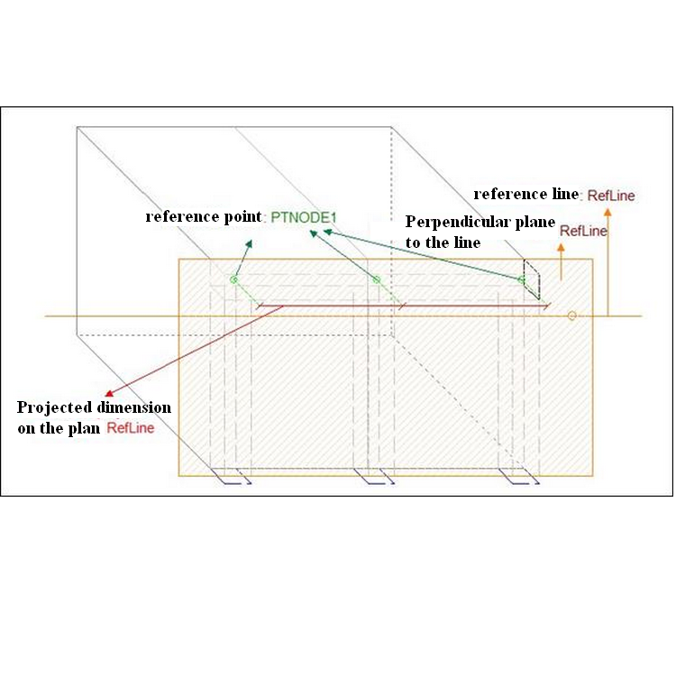
Definition of the reference lines to the bars
This step will define the position of the dimension that will be generated
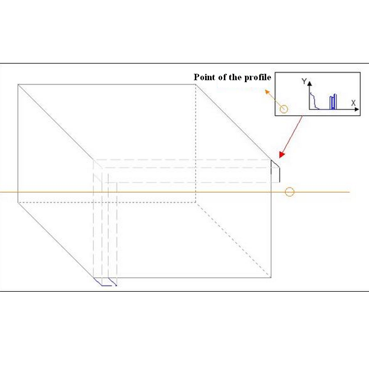
This information is defined by means of an action of type "Action for defining a reference line to the bar" which is associated with the bar stack(s) by means of a procedure of type "Reference line procedure".
-
Step 1 : Bar reference line definition action
-
Step 2 : Creating the reference line procedure
Put the bar reference line definition action in a reference line procedure
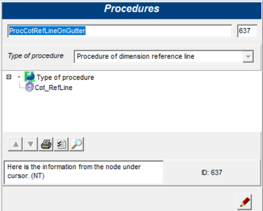
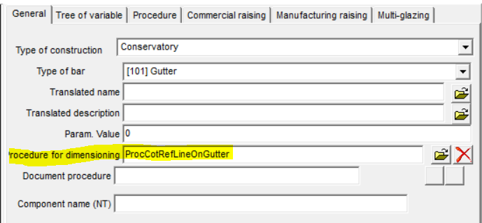
- Step 3 : Association of the procedure with the bar stack(s) :
Associating the Dimension Reference Line procedure in bar stacks
Creation of dimensions based on points and lines
This step will allow you to define the type of dimensioning you wish to obtain on the basis of the reference points and lines (steps 1 and 2)
- Step 1 : Creation of quotation actions
The purpose of these actions is to define how the dimension will be generated based on the reference points and lines (see points 1 and 2).
I. Linear dimensioning :
→ Use of reference points and lines
This type of dimension is defined by means of an action of the "Linear dimension action" type, which is associated with an automatic view thanks to a procedure of the "Dimension definition procedure" type
Dimensioning perpendicular to a plane
Dimensioning action perpendicular to the reference plane
Remark Leader line
- Parameter in quotation actions
- Value
- 0 or NoLine : no Leader line
- -1 or UntilPoint : Leader line starting from the dimension at the reference point.
- other value : size define in mm
- Example
- UntilPoint = 100%
- UntilPoint/10 = 10%
- -1 = 100%
- -5 = 500%
- -0.1 = 10%
- Value