Naming of variables
By convention, variable names begin with a prefix beginning with V followed by characters to determine the type of variable used
| Variable | QUICK NAME |
|---|---|
| Variable of type value | VVA_ |
| Type variable yes/no (Yes/No) | VYN_ |
| Variable of type Value list | VLV_ |
| Variable of type Text List | VLT_ |
| Variable of type Material list | VLA_ |
| Variable of type Material list per row | VLAL_ |
The rest of the variable name is based on English (see Technical Glossary FR-EN) and corresponds to the descriptive part of the variable. On the basis of this information, the parameterizer must be able to understand the meaning of the variable and the framework of its use in the parameterization.
Important Avoid the use of +,-,/,* characters in variable names because these characters are recognized. by the expression generator as arithmetic operators which implies that it is necessary to use the "" to process them in expressions (s.variable_interger("var-xxx") without get an error message
Convention for the presentation of variables
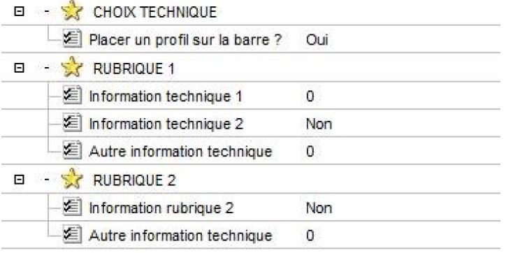
Presentation of information
- Name of the headings: in CAPITAL LETTERS
- Variable text: first letter in upper case - the rest in lower case
Result
Preparation of profile images to be associated with a variable
Important Layer organization in X2d files
- First layer: graphic information
- Second layer: French texts
- Third layer: Dutch texts
- Fourth layer: English texts
- … For this reason, it is strongly advised to avoid putting comments to be translated. in the illustrations
Creating the image of the section in *.x2d format
For all profiles (frames, sashes, transoms, ...), prepare the image by proceeding as follows next:
- Copy the *.X2d file of the section
- Delete polygons from the simplified section
- Colour the thermal strips black
- Add profile reference (red)
- Indicate the general dimensions of the profile (see info in the catalog - Dimensions useful)
Important
The images must be prepared using the same color dimensions, font size, scale so that the presentation is consistent when the user scrolls through the list of profiles in the the list.
Variable of type text list
- Associate the *.x2d file with the text of the variable
Variable of type material list
- Associate the *.x2d file in the article
- In the Xlib menu: Database\Articles\Edition
- In the general information of the window for editing an article, left-click in the area "Image"
Note: If the image does not seem to be associated with the article, check the length of the corresponding field
- In the Xlib: Tools menu\modify the length of the fields
- Search for "Name of the image file of an item" and define the size of the field (Attention max 255 characters)
File organization
Organize the images in the : \picture\X2d_Articles\Article_xxx.x2d where xxx corresponds to the profile reference (This directory is a sub-directory of the current vendor)
Important
For technical reasons, the Project Authority may indicate agreements to project-specific file naming and organization. Always refer to the library's setup conventions when working with the library for naming conventions and organization of library images.
Preparation of descriptive images for associate with variables
Important Layer organization in X2d files
- First layer: graphic information
- Second layer: French texts
- Third layer: Dutch texts
- Fourth layer: English texts
- …
For this reason, it is strongly advised to avoid putting comments to be translated. illustrative
Creating the image in *.jpg format
If the images do not contain text to be translated (only references and/or quotations), the images can be prepared in *.jpg format The height of these images will be between 150 and 300 pixels The width of these images will be between 150 and 300 pixels.
Creating the image in *.x2d format
For images that contain text to be translated, the image must be in *.x2d format The texts to be translated will be placed in the layers as indicated above.
Image creation agreement
Important The images must be prepared using the same color dimensions, font size, scale so that the presentation is consistent when the user scrolls through the list of profiles in the the list.
Colour convention
-
If possible, the background of the drawing should be white.
-
If the image consists of several elements, the descriptive element of the variable will be highlighted by a colorization in fuschia (color that corresponds to the selection in Cover)
- Fill color of element (section, object, ...) = RGB: 255-0-255
- Line color of the element (section, object, ...) = RGB: 210-0-210
-
For the elements that depend on the internal/external visualization of the structure, the following should be used
-
Cover's standard colouring conventions
- Interior color (Pink) = RGB: 255-128-128
- Interior color (Blue) = RGB: 147-201-255
-
References are shown in Arial font (dark blue) RGB: 0-0-75 - size of 200 (in Cover) from 18 in a drawing tool like "Paint.exe".
-
The quotations are drawn in blue RGB: 0-0-255 - Arial Text Important Texts embedded in images must never refer to variable names! This is information that means nothing to the end user. It is preferable to use abbreviations such as H, L,... that help to identify the processed information
Note: If the image does not seem to be associated with the item, check the length of the corresponding field
- In the Xlib menu: Tools\database\change the length of the fields
- Search for "Name of the image file of an item" and define the size of the field (Attention max 255 characters)
File organization
Organize the images in the : \picture\XXX\YYYYY\V_ZZZ.x2d where
- XXX corresponds to the type of structure
- YYY is the name of the series
- ZZZ is the name of the variable (or user choice)
- (This directory is a subdirectory of the current supplier)
Important For technical reasons, the Project Authority may indicate agreements to project-specific file naming and organization. Always refer to the library's parameterization conventions while working. for naming conventions and organization of library images.
Parameter value
It is best to use the quantify function to test the parameter values. Reminder the use of the "quantify" function (see XLib.chm manual) allows an evolution of the parameter value through work progress.
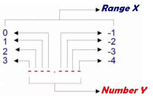
This function accepts two parameters, the number to be processed (denoted Y) and the index of the number to be received. (noted X) : Quantify(Y;X). It then returns the rank digit X in Y. Important
The default value of a parameter value = 0 Therefore, you should never do a "paramvalue = 0" type test for a particular case for which you have to would have set the parameter value to 0 - never assume that the parameter value will be different from 0 in all other cases
Important
The parameter values are linked to the library being processed. Please refer to the supplier's parameterization convention for the meaning of the parameter values used in the library. This involves updating the history of the library during the evolution of the parameterization
Important
The parameter values of the series and construction models are linked to the treated library Refer to the task of creating the series or building model for the parameter values to be used in the library. Never test on MODEL=0 or SERIES=0 - 0 is the default value.
Important
In general, for profiles positioned at the mesh (side 1, 2, 3, 4)- the parameter value is defined at the level of the unit digit and corresponds to the mesh number on which it is extruded - 0 is the default entry.
Denomination and use of points on the sections
General
- Position point (profile insertion) Position point (Cover point)
- Hook point (destination point)
- If there is only one hook point, use the cover points
- Point of attachment
- Hanging point left
- Right hook point
- If there is only one hook point, use the cover points
- If a specific hook point is used, use a user point named according to the convention :
P_CON_xxx
-
P = Point
-
CON = Connection
-
xxx = Ref or Profile information
-
_L or _R can be added as a suffix to the name to distinguish between left (_L) and right (_R) point. rights (_R)
-
If there is a point of attachment for placing the gaskets : P_CON_GASKETi
-
P = Point
-
CON = Connection
-
GASKETi -> GASKET=Gasket and i = Gasket identification number (=0,1,...)
-
_L or _R can be added as a suffix to the name to distinguish between left (_L) and right (_R) point. rights (_R)
Rating point
- Dimensioning point1 (cover point)
- Positions in the chassis:
- Outside frame
- Exterior Opening
- Traverse Axis
- Interior glazing bead
Denomination and use of lines on sections
General
| Use case | Denomination |
|---|---|
| Identification | L_ID_xxx |
| Thrust | L_TH_xxx |
| Bevel | L_BV_L_xxx or L_BV_R_xxx L (or R) = Left (or Right) distinguishes the left or right line for the bevel |
Naming and organization of objects texts
Important
the names of text objects cannot contain
- special characters
- mathematical characters (+, -, /, *, ..)
- of space
- signed characters (é, è, à, ...)
Group organization
The texts are divided into groups according to the scope of their use The convention of the denominations of the groups is as follows:
- PARAM: the texts used by default (Txt_...)
- MESSAGE: the texts used for messages
- SERIES: the texts used for the construction models
- REBATES: the texts used for rebates
- VAR: the texts used for the variables (trees)
- The texts for the values of the choices of a variable are stored in a subgroup with the variable name
For example:
- VAR
- VLT_W_VAR_CHOICE (variable of type text list)
- VLT_W_VAR_CHOICE (group)
- Txt_Choice1
- Txt_Choice2
- Txt_Choice3
| Use case | Denomination |
|---|---|
| translated descriptions | desc_xxx |
| translated names | name_xxx |
| message | msg_xxx |
| discounts | reb_xxx |
Denomination of stack variables
Prefix:
- Stack: Stack_
- GS battery: GS_
- PGS battery: PGS_
Name of shares
General
The name associated with an action must be descriptive of what distinguishes it from the default definition of The name of the action is therefore composed of a prefix corresponding to the type of action processed. and a sequence of information specifying the characteristics of the action. Where an action involves a stack variable value, the name of the action must contain the following information describing:
- the stack parameter
- the type of battery called
- S: Stack
- GS : GS
- PS : PS
- the stack variable called
Example: POS_X-GS-VDX_Y-GS-VDY_Z-GS-VRZ
describes a position action whose parameters DX, DY and RZ are defined on the GS stack. respectively by the variables V_DX, V_DY, V_RZ Definition by action type
- Profile
- Assembly
- Filling
- Accessories
- Hardware store
- 3D Wired
- Machining
Action Profiles
| Use Case | Denomination |
|---|---|
| position action | POS_xxx |
| Positioned profile action | EXT_xxx |
| Offset profile positioning action with a length | APPNODE_xxx |
| Placement of a profile at a cut-off point | PPC_xxx |
Group organization
- Profiles: groups actions relating to profiles/joints
- Position: Groups together the profile position actions
- Default: Groups the "standard" position actions (X0_Y0_Z0, X0_Y0_Z0_MH, ...)
- ConstructionType: one group per type of construction to be implemented in the library / Window / CompoW / Conservatory / Gate / Curtain Wall
- Default: Groups the "standard" position actions for the construction type.
- Gasket: Regroups the position actions of the joints
- Fictitious: Groups together the shares of positions for the fictitious ones.
- ModelName: Groups position actions by construction model
- BeamType: Groups position actions by bar type
- Extrusion: Groups the actions of profile positioned
- ConstructionType: one group per type of construction to be implemented in the library / Window / CompoW / Conservatory / Gate / Curtain Wall
- Gasket: Regroups the profile actions positioned of the joints
- Fictitious: Groups together fictitious positioned profile shares
- ModelName: Groups the profile actions positioned by construction model
- BeamType: Groups profile actions positioned by bar type
- APPNode: Regroups the positioning actions of the off-axis profile with length
- ConstructionType: one group per type of construction to be implemented in the library / Window / CompoW / Conservatory / Gate / Curtain Wall
- ModelName: Groups the positioning actions of off-axis profile with length by construction design
- PCaesura: Groups investment shares from a profile to a caesura
- ConstructionType: one group per type of construction to be implemented in the library / Window / CompoW / Conservatory / Gate / Curtain Wall
- ModelName: Groups investment stocks from a profile to a caesura by model of construction
- Position: Groups together the profile position actions
Action - Assembly
| Action type | Denomination |
|---|---|
| Bevel action | BV_xxx |
| Bevel Action + Cutting | BVC_xxx |
| Single stop action | TH_xxx |
| Double stop action | TH2_xxx |
| Stop Action on Node Accessory | THAN_xxx |
| Stop action with parameter value | THPV_xxx |
| Profile lengthening action | LP_xxx |
| Embeding action | EMB_xxx |
| Action follows plans profile cuts | SA_xxx |
| Action union profile | UP_xxx |
| Profile deletion action by a node | DPN_xxx |
Group organization
- Assembly: groups together the assembly actions
- ConstructionType: one group per type of construction to be implemented in the library
- Window - CompoW - Conservatory - Gate - Curtain Wall
- ModelName: Groups assembly actions by construction model
- ActionType: Groups assembly actions by ActionType - the name of the group corresponds to the prefix of the name of the action of this type
- Bi-Bj: For actions requiring the intervention of 2 bars, it is advisable to use them classify by grouping them according to the index of the bars (i= index of the first bar).
bar - j=indice of the 2nd bar in the action)
Accessories
| Use Case | Denomination |
|---|---|
| Action placement of accessory on accessory | APA_xxx |
| Fixed repetition accessory action | ARF_xxx |
| Accessory action repeat max-min step | ARMM_xxx |
| Length accessory action | AL_xxx |
| Knot accessory action | AN_xxx |
Group organization
- Accessories: Groups together the positioning actions of accessories
- ConstructionType: one group per type of construction to be implemented in the library
- Window - CompoW - Conservatory - Gate - Curtain Wall
- ModelName: Groups the accessory positioning actions by model of construction
- ActionType: Groups accessory positioning actions by Action Type
- the group name corresponds to the prefix of the action name of this type
Hardware
as Accessories with the exception of the first letter: A becomes H (Hardware)